Nitride phosphor and production process thereof, and light emitting device
A technology of phosphors and silicon nitrides, which is applied in chemical instruments and methods, luminescent materials, semiconductor devices, etc., and can solve problems such as the influence of color image tone
- Summary
- Abstract
- Description
- Claims
- Application Information
AI Technical Summary
Problems solved by technology
Method used
Image
Examples
Embodiment approach 1
[0386] The phosphor of the present invention is characterized in that it has the general formula L X M Y N ((2 / 3)X+(4 / 3)Y) : R series or L X M Y O Z N ((2 / 3)X+(4 / 3)Y-(2 / 3)Z) : A nitride phosphor represented by R, and the nitride phosphor contains an element different from the above-mentioned L, the above-mentioned M, the above-mentioned O, the above-mentioned N, the above-mentioned and the R series (hereinafter referred to as "different element")
[0387] Here, L is selected from at least one or more group II elements consisting of Mg, Ca, Sr, Ba, and Zn,
[0388] M is selected from C, Si, Ge, Si is at least one of the necessary group IV elements,
[0389] R is selected from Y, La, Ce, Pr, Nd, Sm, Eu, Gd, Tb, Dy, Ho, Er, and Lu. Eu is at least one of the essential rare earth elements.
[0390] In the general formula, X, Y, and Z are arbitrary numbers greater than zero. In particular, X and YX=2, Y=5 or X=1 and Y=7 are preferable. Specifically, (Sr T Ca 1-T ) 2 Si 5 N 8 : Eu, Sr 2 ...
Embodiment approach 2
[0480] The light-emitting device of Embodiment 2 is the same as Embodiment 1, and has at least:
[0481] A light-emitting element having a first emission spectrum; and
[0482] The phosphor converts at least a part of the first emission spectrum to wavelength and has a second emission spectrum.
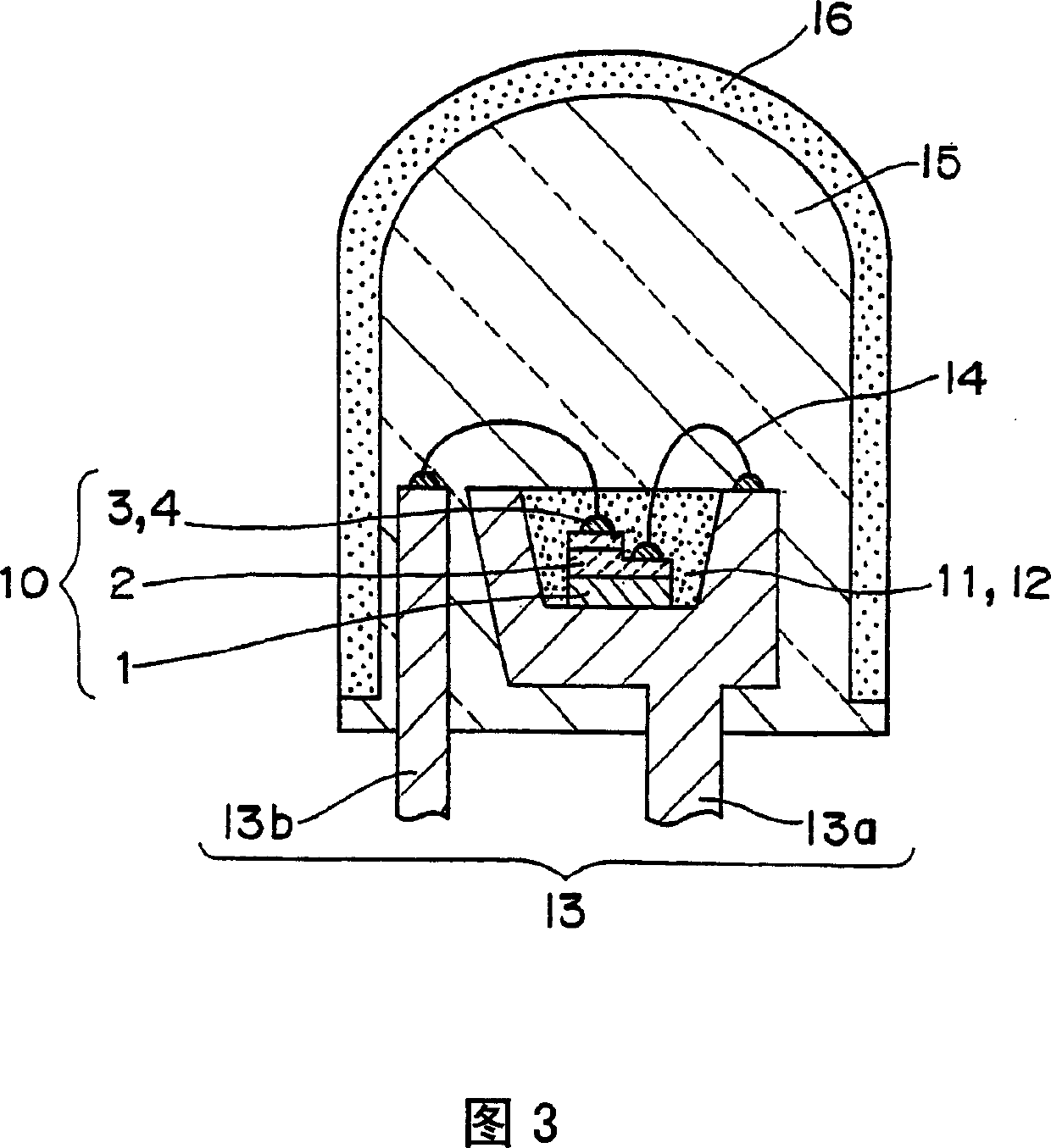
[0483] The light-emitting device of the second embodiment uses only a nitride phosphor described later as the phosphor 11, for example. The phosphor 11 absorbs part of the light in the ultraviolet to blue region that is emitted by the light emitting element 10, and emits the light in the yellow to red region. The light-emitting device of the second embodiment uses the phosphor 11 in the light-emitting device of type 1, and according to the mixture of the blue color of the light-emitting element 10 and the red color of the phosphor, the warm color white or pink A light-emitting device that emits light with a soft color. The light-emitting device of Embodiment 2 is a light-emitting device t...
Embodiment approach 3
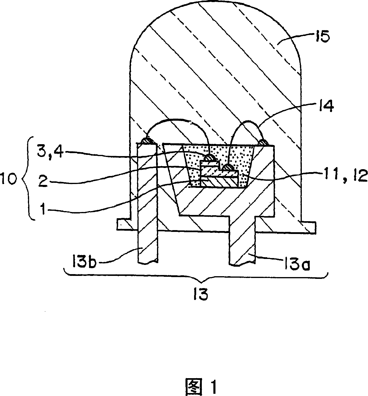
[0506] The light-emitting device according to the third embodiment of the present invention is a light-emitting device of form 1 (cannonball type) shown in FIG. 1, and has the same configuration as that of the first embodiment except that a phosphor described later is used.
[0507] Hereinafter, the phosphor of the light-emitting device of the present invention will be described in detail.
[0508] The phosphor of the third embodiment of the present invention is LMN:Eu, WR series or LMON:Eu, WR series (L contains at least one selected from the group consisting of Be, Mg, Ca, Sr, Ba, and Zn valence II One or more. M contains at least one selected from the group consisting of C, Si, Ge, Sn, Ti, ZR, and Hf with IV valence. N nitrogen. Eu is europium. WR is rare earth other than Eu Class element).
[0509] The following description relates to the phosphor of the third embodiment of the present invention, mainly Ca-Si-N:Eu, WR series, or Sr-Si-N:Eu, WR series, or Sr-Ca-Si-N:Eu , WR ser...
PUM
| Property | Measurement | Unit |
|---|---|---|
| The average particle size | aaaaa | aaaaa |
| The average particle size | aaaaa | aaaaa |
| Luminescence peak | aaaaa | aaaaa |
Abstract
Description
Claims
Application Information
 - R&D
- Intellectual Property
- Life Sciences
- Materials
- Tech Scout
- Unparalleled Data Quality
- Higher Quality Content
- 60% Fewer Hallucinations
Browse by: Latest US Patents, China's latest patents, Technical Efficacy Thesaurus, Application Domain, Technology Topic, Popular Technical Reports.
© 2025 PatSnap. All rights reserved.Legal|Privacy policy|Modern Slavery Act Transparency Statement|Sitemap|About US| Contact US: help@patsnap.com


