Leakage-checking spacing method of blast furnace

A cooling wall and leak detection technology, applied to the cooling device, by detecting the appearance of fluid at the leakage point, and by measuring the increase and deceleration rate of the fluid, it can solve the problems of low efficiency, slow speed, unfavorable safety production, etc., to avoid The effect of burning loss, reducing labor intensity and improving labor efficiency

Inactive Publication Date: 2006-08-16
HEBEI IRON AND STEEL
View PDF0 Cites 15 Cited by
  • Summary
  • Abstract
  • Description
  • Claims
  • Application Information

AI Technical Summary

Problems solved by technology

This method is used to check for leaks on the cooling wall, which is slow and inefficient. Moreover, at the initial stage of closing the water inlet valve of the cooling wall and opening the exhaust valve, the...

Method used


Image

  • Leakage-checking spacing method of blast furnace

Examples


Embodiment Construction

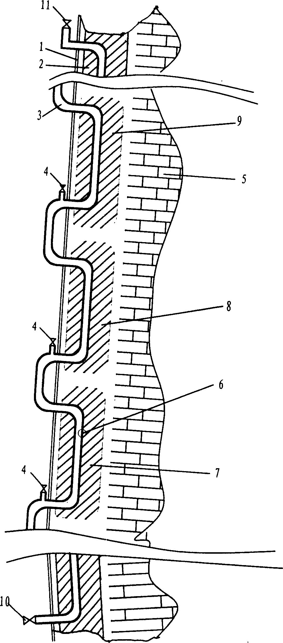
[0018] This embodiment is a blast furnace with closed circulation of soft water. There are 13 sections of cooling walls from the furnace hearth to the top of the furnace body. The water supply method is connected in series from bottom to top. refer to figure 1 , which is a schematic diagram of the longitudinal section structure of the cooling staves in the same column from the seventh to ninth sections of the blast furnace. The method for leak checking and determining section of the present invention is carried out as follows:

[0019] (1). Determine the column where the damaged cooling wall is located: adopt the flow method commonly used in production at present, that is, when the water inflow and output difference of a column cooling wall is greater than the normal standard value, and the H in the gas 2 The content is 1%-2% higher than the normal value, and the temperature of the furnace wall at the location of the cooling wall in this column drops more than the normal valu...


PUM


Abstract

A method for detecting out leakage and its position on cooling wall of blast furnace includes confirming line existed by damaged cooling wall, blocking water supply of said line, supplying air on water supply tube and opening air vent valve at top section of cooling wall, leading compressed air with pressure greater than pressure in furnace in water supply tube on said cooling wall, opening air vent valve on adjacent cooling wall to see whether there is water being led out or not then opening said valve on cooling wall of the line in sequence till water is led out at one of valves ,confirming that section above water-out valve is damaged .

Description

technical field [0001] The invention relates to a leak detection method for a blast furnace cooling system, and belongs to the technical field of maintenance methods for blast furnace ironmaking equipment. Background technique [0002] The blast furnace stave is a cooling device installed between the steel shell of the blast furnace and the refractory lining along the height of the blast furnace, with water pipes cast inside and cooling water flowing through it. Its function is to cool the refractory lining of the blast furnace, and at the same time prevent the strong heat flow in the furnace from acting on the furnace shell to cause deformation and cracking. The staves arranged at the same height of the blast furnace and distributed along the circumference of the furnace body form a section, the upper and lower sections are connected in series, and the staves connected in series from bottom to top form a row. In the long-term high-temperature working environment, especiall...

Claims


Application Information

Patent Timeline
IPC IPC(8): G01M3/06G01M3/26C21B7/10
Inventor 王卫峰刘根
Owner HEBEI IRON AND STEEL
Why Eureka
Try Eureka