Motor vehicle coolant circuit comprising a pump and a retarder

A coolant circuit and reducer technology, which is applied in engine cooling, liquid cooling, coolant flow control, etc., can solve problems such as increasing fuel consumption, increasing weight, and increasing power consumption of coolant pumps

Inactive Publication Date: 2006-08-30
VOITH PATENT GMBH
View PDF0 Cites 14 Cited by
  • Summary
  • Abstract
  • Description
  • Claims
  • Application Information

AI Technical Summary

Problems solved by technology

[0005] The driving of high-power coolant pumps requires more energy, thereby increasing the fuel consumption of the vehicle
The particular consequence of this is that there is an increased power consumption of the coolant pump even when the gear unit is not switched on at all, e.g. when the gear unit is empty
However, compared with normal car driving (without the use of retarder brakes), the use of the reducer is usually only in a relatively short period of time.
Last but not least, using a powerful coolant pump means adding extra weight to the car, which likewise increases fuel consumption

Method used


Image

  • Motor vehicle coolant circuit comprising a pump and a retarder
  • Motor vehicle coolant circuit comprising a pump and a retarder
  • Motor vehicle coolant circuit comprising a pump and a retarder

Examples


Embodiment Construction

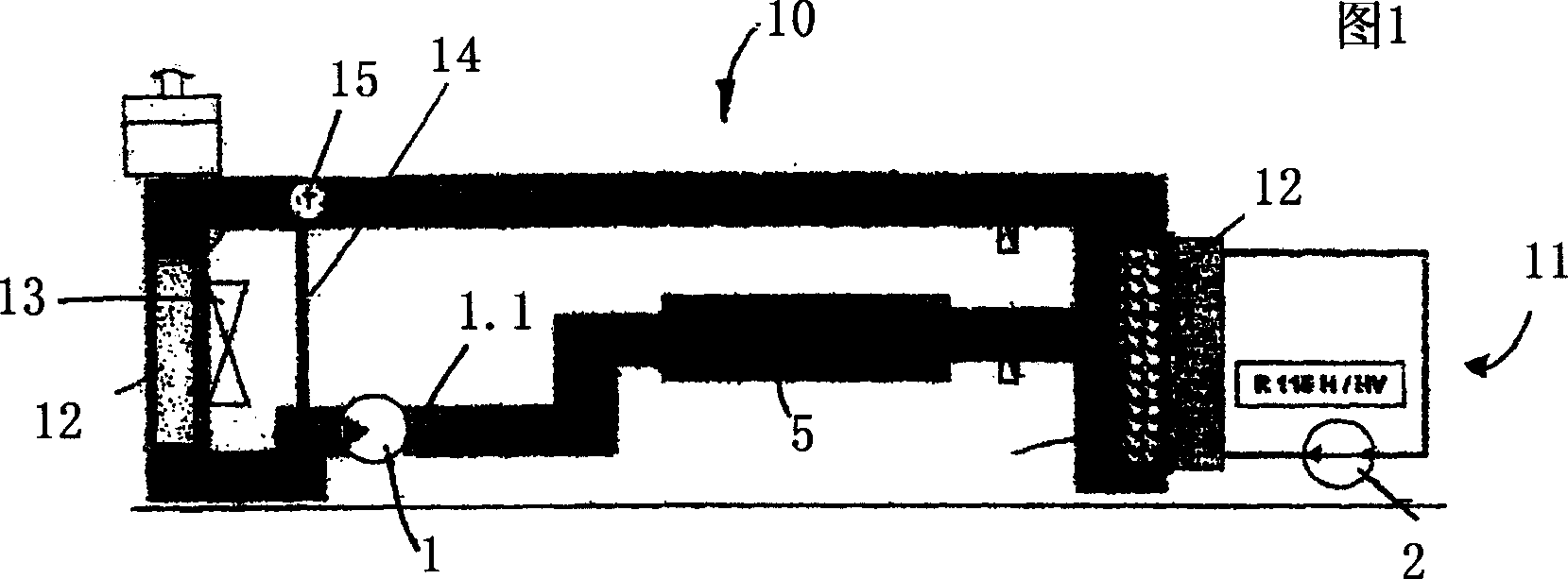
[0020] A coolant circuit 10 and a gear unit operating medium circuit 11 can be seen in FIG. 1 . According to the prior art, the two circuits are implemented separately. The coolant circulates in the coolant circuit 10 by means of the coolant pump 1 , and the working medium in the gear reducer working medium circuit 11 circulates by means of the gear reducer 2 . The two circuits are connected to each other by means of an oil-water heat exchanger 12 so that the heat generated in the gear unit 2 can be transferred into the coolant circuit 10 . Conventionally, heat is dissipated from the coolant circuit 10 by means of a radiator 12 and a blower wheel rotor 13 . As long as it is not necessary to dissipate heat energy from the coolant circuit 10 for reasons of the coolant temperature, the coolant bypasses the radiator via the bypass 14 . A thermostat 15 is provided for proper adjustment.

[0021] The cooling fluid flow required for energy transfer, especially the cooling water fl...


PUM


Abstract

The invention relates to a coolant circuit of a motor vehicle, comprising: a coolant, especially water or a water mixture; a coolant pump having a coolant outlet; a retarder provided with a central ring, the working medium thereof being the coolant; a reversing valve in the flow direction upstream of the retarder, and a bypass section for bypassing the retarder, such that the retarder can be connected to and disconnected from the coolant circuit. According to the invention, the coolant pump is arranged in the flow direction, upstream of the retarder, in such a way that it pumps coolant into the retarder when the retarder is connected, and pumps coolant past the retarder via the bypass section when the retarder is disconnected. The inventive motor vehicle coolant circuit is characterised in that, when the retarder is connected, the total flow resistance from the outlet of the coolant pump to the central ring of the retarder is lower than the total flow resistance of the coolant circuit to be overcome by the coolant pump in the non-braking mode.

Description

technical field [0001] The present invention relates to a circuit for vehicle coolant, said system comprising both a coolant pump and a retarder, wherein the working medium of the retarder is coolant. Background technique [0002] Traditionally, hydraulic oil is used as the working medium of the reducer in the automobile transmission system. Consider that the hydraulic oil must be cooled due to the heat generated during brake mode operation. For this purpose, an oil-water heat exchanger is usually provided as an interface between the cooling circuit and the retarder working medium circuit, via which the necessary heat is introduced from the retarder circuit into the cooling circuit of the vehicle. [0003] More recently, gear units are also known which are arranged directly in the conventional vehicle coolant circuit and whose working medium is the cooling medium in the cooling circuit. Arranging such a reducer in the cooling circuit increases the total flow resistance or ...

Claims


Application Information

Patent Timeline
Patent Type & Authority Applications(China)
IPC IPC(8): F01P3/20B60T1/087F16D57/04B60T10/02F01P7/14F02N19/10
CPCF01P2007/146F16D57/04F16D57/005F01P3/20B60T10/02B60T1/087
Inventor 克劳斯·福格尔桑
Owner VOITH PATENT GMBH
Why Eureka
Try Eureka