
Manufacturing method of in-connection and manufacturing method of composite dielectric barrier-layer

A technology of dielectric barrier and manufacturing method, applied in semiconductor/solid-state device manufacturing, circuits, electrical components, etc., can solve problems affecting process reliability and yield, improve process reliability and prevent outward diffusion , The effect of improving reliability and yield

Inactive Publication Date: 2006-09-13
UNITED MICROELECTRONICS CORP
View PDF0 Cites 9 Cited by
  • Summary
  • Abstract
  • Description
  • Claims
  • Application Information

AI Technical Summary

Problems solved by technology

Wherein, these tiny holes (including cracks and small holes) will become the leakage (leakage) path, for example, the acidic solution or gas used in the subsequent process, such as etchant or etching gas in the etching process, then The copper surface will be corroded along these holes, and copper metal is also easy to diffuse outward from these holes, which will seriously affect the reliability and yield of the process

Method used


Image

  • Manufacturing method of in-connection and manufacturing method of composite dielectric barrier-layer
  • Manufacturing method of in-connection and manufacturing method of composite dielectric barrier-layer
  • Manufacturing method of in-connection and manufacturing method of composite dielectric barrier-layer

Examples


Embodiment Construction

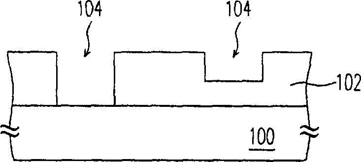
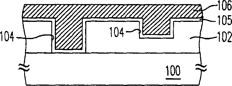
[0031] Figure 1A to Figure 1G What is shown is a schematic cross-sectional flow diagram of the manufacturing method of the interconnection line according to the preferred embodiment of the present invention.

[0032] First, please refer to Figure 1A , providing a substrate 100 in which elements (not shown) have been formed. Next, a dielectric layer 102 is formed on the substrate 100. The material of the dielectric layer 102 is, for example, silicon oxide, and the formation method is, for example, chemical vapor deposition. In addition, the above-mentioned dielectric layer 102 can be formed of one layer or multiple layers of dielectric material, which can be adjusted according to the circuit design requirements in the process.

[0033] Then, please refer to Figure 1B , forming a plurality of openings 104 in the dielectric layer 102, and these openings 104 can be filled with conductive material in subsequent processes to be used as interconnection lines. Wherein, the formi...


PUM


Abstract

This invention relates to a manufacturing method for internal connection lines including providing a dielectric layer with many open-ends in it, then forming a metal layer to full-fill these open-ends then forming a first dielectric blocking layer to cover the dielectric and the metallic layers, after that, forming a second dielectric blocking layer on the first to mend the first one to increase the reliability and productivity of the technique.

Description

technical field [0001] The invention relates to a semiconductor process, in particular to a method for manufacturing an interconnection line and a method for manufacturing a composite dielectric barrier layer. Background technique [0002] With the rapid development of the integrated circuit industry, relative to the miniaturization of components and the increase in integration, the surface of the chip cannot provide enough area to make the required metal interconnection. Therefore, in order to meet the requirement of increasing the metal interconnection after the device is scaled down, a design of more than two metal layers has been developed. In particular, some products with relatively complex functions, such as microprocessors, even require four to five layers of metal layers to complete the connection between the various components. [0003] Because metal copper has high electromigration resistance (electromigration resistance) and low resistance, which can allow reduc...

Claims


Application Information

Patent Timeline
Patent Type & Authority Applications(China)
IPC IPC(8): H01L21/768H01L21/3205H01L21/314
Inventor 吴一经陈明德萧志祥陈彦竹陈先亿
Owner UNITED MICROELECTRONICS CORP
Learn More