A high-power charging connector cooling device for new energy vehicles

A technology for high-power charging and new energy vehicles. It is applied in the direction of electric vehicle charging technology, charging stations, electric vehicles, etc. It can solve the problems of cable heat dissipation, cooling liquid heat limitation, and cooling liquid temperature rise, etc., to ensure reliability And the safety of work, uniform and long-lasting cooling effect, and the effect of preventing leakage from spreading outward

Active Publication Date: 2021-09-17
CHINA UNIV OF MINING & TECH
View PDF9 Cites 0 Cited by
  • Summary
  • Abstract
  • Description
  • Claims
  • Application Information

AI Technical Summary

Problems solved by technology

[0002] In order to shorten the charging time of new energy vehicles, more and more car companies use high-voltage and high-current methods for high-power charging, which brings about the consequences of excessive heat accumulation and poor heat dissipation in the charging gun head and charging cable. , seriously restricting the development of car charging in the direction of safety and efficiency
[0003] Chinese patent application CN208589277 U proposes a cable for a high-power charging gun with a cooling function. By arranging a cooling pipe inside the cable, it is further connected to a circulating cooler to form a cooling circuit. However, the distance of the cooling circuit in the cable is very long, resulting in The temperature of the coolant continues to rise, which limits the heat that the coolant can take away and the uneven heat dissipation of the cables
Chinese patent application CN207416561U proposes a charging gun with heat dissipation function. Cooling flow passages and cooling pipes are arranged in the charging gun, and the heat inside the charging gun can be dissipated rapidly through the continuously flowing cooling medium, but it does not enter the charging gun. Further cooling is done before the terminal to improve the heat dissipation effect of the terminal, and there is no further cooling when the coolant flows out of the terminal, which causes the temperature of the coolant to flow back into the cable to be too high, which has a great impact on the heat dissipation of the cable, and the above-mentioned patent scheme lacks simplicity. Rapid Leak Detection Method

Method used


Image

  • A high-power charging connector cooling device for new energy vehicles
  • A high-power charging connector cooling device for new energy vehicles
  • A high-power charging connector cooling device for new energy vehicles

Examples


Embodiment Construction

[0027] The following will clearly and completely describe the technical solutions in the embodiments of the present invention with reference to the accompanying drawings in the embodiments of the present invention. Obviously, the described embodiments are only some, not all, embodiments of the present invention. Based on the embodiments of the present invention, all other embodiments obtained by persons of ordinary skill in the art without making creative efforts belong to the protection scope of the present invention.

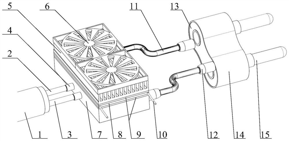
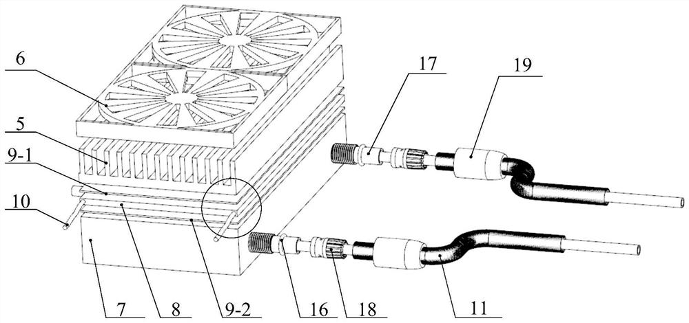
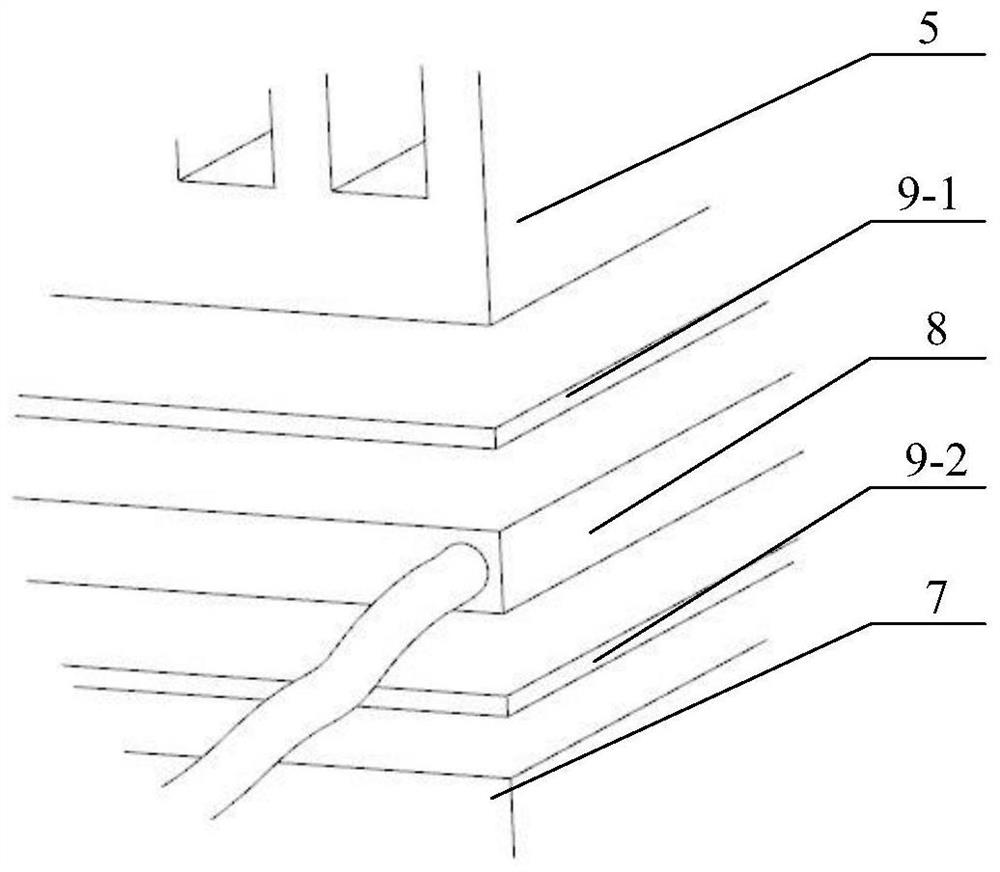
[0028] Such as Figure 1 to Figure 6 As shown, a high-power charging connector cooling device for new energy vehicles includes a cooling plate 7, a cable 1 with two cooling inner tubes 2, a terminal cooling plate 13, and insulating and heat-conducting silica gel at the cold end and the hot end respectively. The thermoelectric cooling sheet 8 of the sheet 9, the two cooling inner pipes 2 are the water inlet pipe and the water outlet pipe respectively, which are...


PUM


Abstract

The invention discloses a high-power charging connector cooling device for new energy vehicles, which includes a cable, a heat sink, a thermoelectric cooling plate, a cooling plate, a cooling inner tube, an outer tube, and a terminal cooling plate; the cooling inner tube is designed inside the cable, Pass through the cooling plate and then be sealed with the terminal cooling plate. The interior of the terminal cooling plate is a hollow flow channel, and a leak detection sensor is installed between the terminal cooling plate and the cooling plate; Fully refrigerate the cooling liquid; the cooling device has the advantages of fast heat dissipation, anti-leakage pollution, and convenient leak detection.

Description

technical field [0001] The invention relates to the field of new energy vehicles, in particular to a high-power charging connector cooling device for new energy vehicles. Background technique [0002] In order to shorten the charging time of new energy vehicles, more and more car companies use high-voltage and high-current methods for high-power charging, which brings about the consequences of excessive heat accumulation and poor heat dissipation in the charging gun head and charging cable. , Seriously restricting the development of car charging in the direction of safety and efficiency. [0003] Chinese patent application CN208589277 U proposes a cable for a high-power charging gun with a cooling function. By arranging a cooling pipe inside the cable, it is further connected to a circulating cooler to form a cooling circuit. However, the distance of the cooling circuit in the cable is very long, resulting in The temperature of the coolant continues to rise, which limits th...

Claims


Application Information

Patent Timeline
Patent Type & Authority Patents(China)
IPC IPC(8): B60L53/302B60L53/16
CPCB60L53/16B60L53/302Y02T10/70Y02T10/7072Y02T90/12Y02T90/14
Inventor 谢方伟徐纯洁田祖织刘秀梅沈刚丁志文
Owner CHINA UNIV OF MINING & TECH
Why Eureka
Try Eureka