
Roller type air intake direct injection engine

A technology of engine and roller, applied in the direction of engine components, engine control, machine/engine, etc., can solve the problems of large opening resistance, complex structure, and poor exhaust, so as to achieve fast exhaust operation speed and reduce exhaust resistance and mechanical wear, and prevent the exhaust valve from being burned out

Inactive Publication Date: 2006-10-04
陈金绪
View PDF0 Cites 0 Cited by
  • Summary
  • Abstract
  • Description
  • Claims
  • Application Information

AI Technical Summary

Problems solved by technology

[0002] At present, the valves of general-purpose engines all use valve seats and valve stems, as well as valve mechanisms including cams and rocker arms. The structure is complex, the cost is high, easy to wear, the opening resistance is large, and the exhaust is not smooth.

Method used


Image

  • Roller type air intake direct injection engine
  • Roller type air intake direct injection engine
  • Roller type air intake direct injection engine

Examples


Embodiment 1

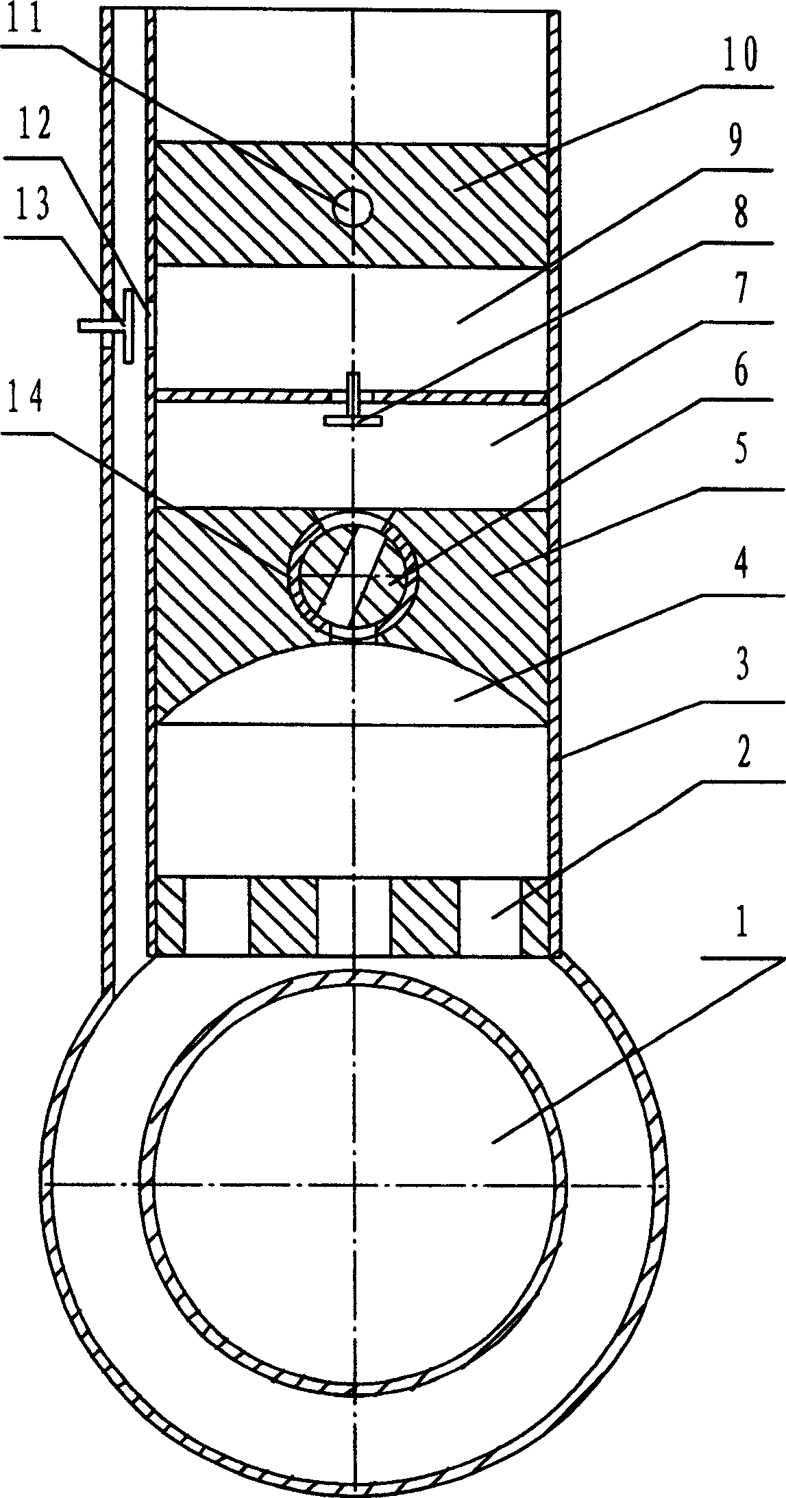
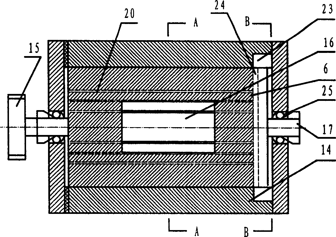
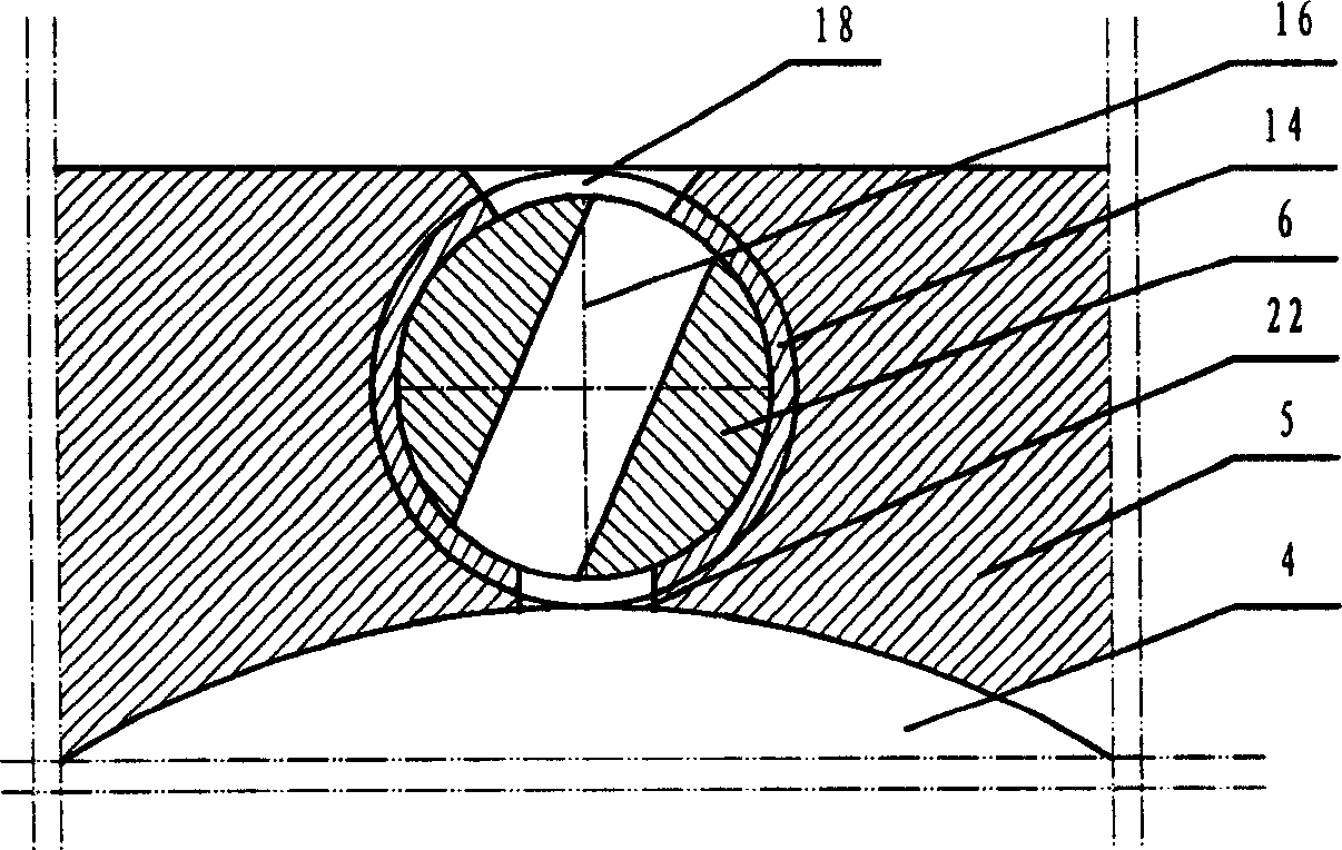
[0025] Embodiment 1, the present invention comprises the cylinder 3 that establishes vent hole 2 and the crankshaft 1 that cooperates with it and piston, establishes the cylinder head 5 of combustion chamber 4 in cylinder 3, is provided with fuel injection nozzle on cylinder head 5, combustion chamber 4 The air intake adopts roller type valve, and described roller type valve is made up of cylinder head 5 and valve roller 6, and valve intake hole 18 is arranged in cylinder head 5, and valve intake hole 18 is provided with valve intake The hole 18 is vertical to the valve roller installation hole, and the valve roller 6 is matched in the valve roller installation hole. The transmission shaft 17 that roller 6 is connected is fixedly connected with transmission wheel 15. When the engine piston goes down to the exhaust hole 2, the exhaust is exhausted, and the roller intake chamber 16 of the valve roller 6 moves to the position where the scavenging hole 22 communicates, so that the...

Embodiment 2

[0026] Embodiment 2: The present invention can also be provided with the oil groove 20 that cooperates with the valve roller 6 on the inner wall of the valve roller installation hole in the valve inlet hole 18, the oil groove 20 communicates with the oil inlet hole, and realizes lubrication and sealing through the oil groove 20 . refer to Figure 1 to Figure 4 , all the other are with embodiment 1.

Embodiment 3

[0027] Embodiment 3: In the present invention, the valve roller sleeve 14 can also be fixedly connected to the outer wall of the valve roller 6 , and the valve roller sleeve 14 is provided with an air inlet hole matching with the valve air inlet hole 18 and the scavenging hole 22 . An oil groove 20 matching the valve roller 6 may also be provided on the inner wall of the valve roller sleeve 14, and the oil groove 20 communicates with the oil inlet hole. refer to Figure 1 to Figure 4 , and the rest are the same as the above-mentioned embodiment.


PUM


Abstract

The invention discloses a roller inflow straight spray engine, which is characterized by the following: the inflow of blast chamber adopts roller air valve; the roller air valve consists of the cylinder head and air valve roller; air valve suction port and scavenge hole are installed in air valve head; the air valve roller assemble hole vertical with air valve suction port is installed in the air valve suction port; the air valve assemble hole is fit for nesting the air valve roller; the roller inflow chamber is installed on the air valve roller, which is fit for the air valve suction port and scavenge hole; the drive axle connects to the air valve roller and power wheel. The invention solves the problems of complex structure, big open drag force and vulnerability, which prevent the air valve burn out.

Description

technical field [0001] The invention relates to an engine, in particular to a direct-injection engine with roller air intake. Background technique [0002] At present, the valves of general-purpose engines all adopt valve seats and valve stems, as well as valve mechanisms including cams and rocker arms, which have complex structures, high costs, easy wear, large opening resistance, and poor exhaust. Contents of the invention [0003] The object of the present invention is to provide a roller type air intake direct injection engine with simple structure, wear resistance and smooth intake and exhaust. [0004] The technical scheme that the present invention adopts to solve its technical problem is: it comprises the cylinder 3 that establishes exhaust hole 2 and the crankshaft 1 that cooperates with it and piston, establishes the cylinder head 5 of combustion chamber 4 in cylinder 3, arranges on cylinder head 5 Fuel injector is arranged, and the air intake of combustion cham...

Claims


Application Information

Patent Timeline
Patent Type & Authority Applications(China)
IPC IPC(8): F02D9/08F02F1/42F01L1/02
Inventor 陈金绪
Owner 陈金绪
Learn More