Rotor for motor and motor

A motor and rotor technology, applied in the direction of magnetic circuit rotating parts, magnetic circuit shape/style/structure, etc., can solve the problems of increased vibration of the rotor 10, low motor characteristics, low durability, etc., to prevent the increase of vibration. Large, high durability, low vibration effect

Active Publication Date: 2006-10-04
SANKYO SEIKI MFG CO LTD
View PDF0 Cites 4 Cited by
  • Summary
  • Abstract
  • Description
  • Claims
  • Application Information

AI Technical Summary

Problems solved by technology

[0005] However, if Figure 5 As shown in (a) and (b), when the cylindrical magnet 20 is thinned, the force preventing the cylindrical magnet 20 from rotating in the circumferential direction relative to the resin portion 30 is only the adhesion between the resin portion 30 and the cylindrical magnet 20. Relay, so when performing temperature cycle tests, etc., such as Figure 5 The dotted line LL in (a), the resin portion 30 shrinks, and a small gap G will be produced between the resin portion 30 and the inner peripheral surface 28 of the cylindrical body 25 of the cylindrical magnet 20, causing the cylindrical magnet 20 to face the resin. part 30 spins
In addition, when the cylindrical magnet 20 is thinned, it is difficult to form irregularities or the like on the inner peripheral surface of the cylindrical magnet 20. As a result, when using Figure 5 When the motors shown in (a) and (b) use the rotor 10 for the temperature cycle test, as image 3 As indicated by the dotted line L2 in , there is a problem that the durability of the motor rotor 10 increases, such as increased vibration
Furthermore, considering the amount of vibration of the motor rotor 10, it is necessary to ensure a large gap between the cylindrical magnet 20 and the stator, so there is a problem that the motor characteristics are low.

Method used


Image

  • Rotor for motor and motor
  • Rotor for motor and motor
  • Rotor for motor and motor

Examples


Embodiment Construction

[0030] Next, preferred modes for carrying out the present invention will be described with reference to the drawings.

[0031] Implementation form 1:

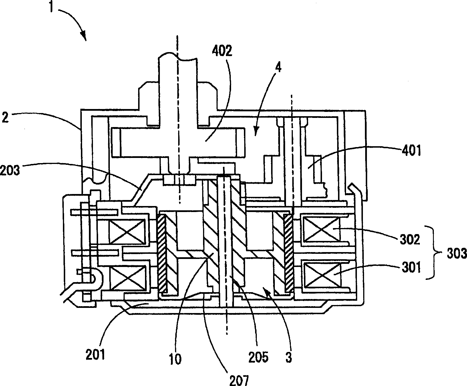
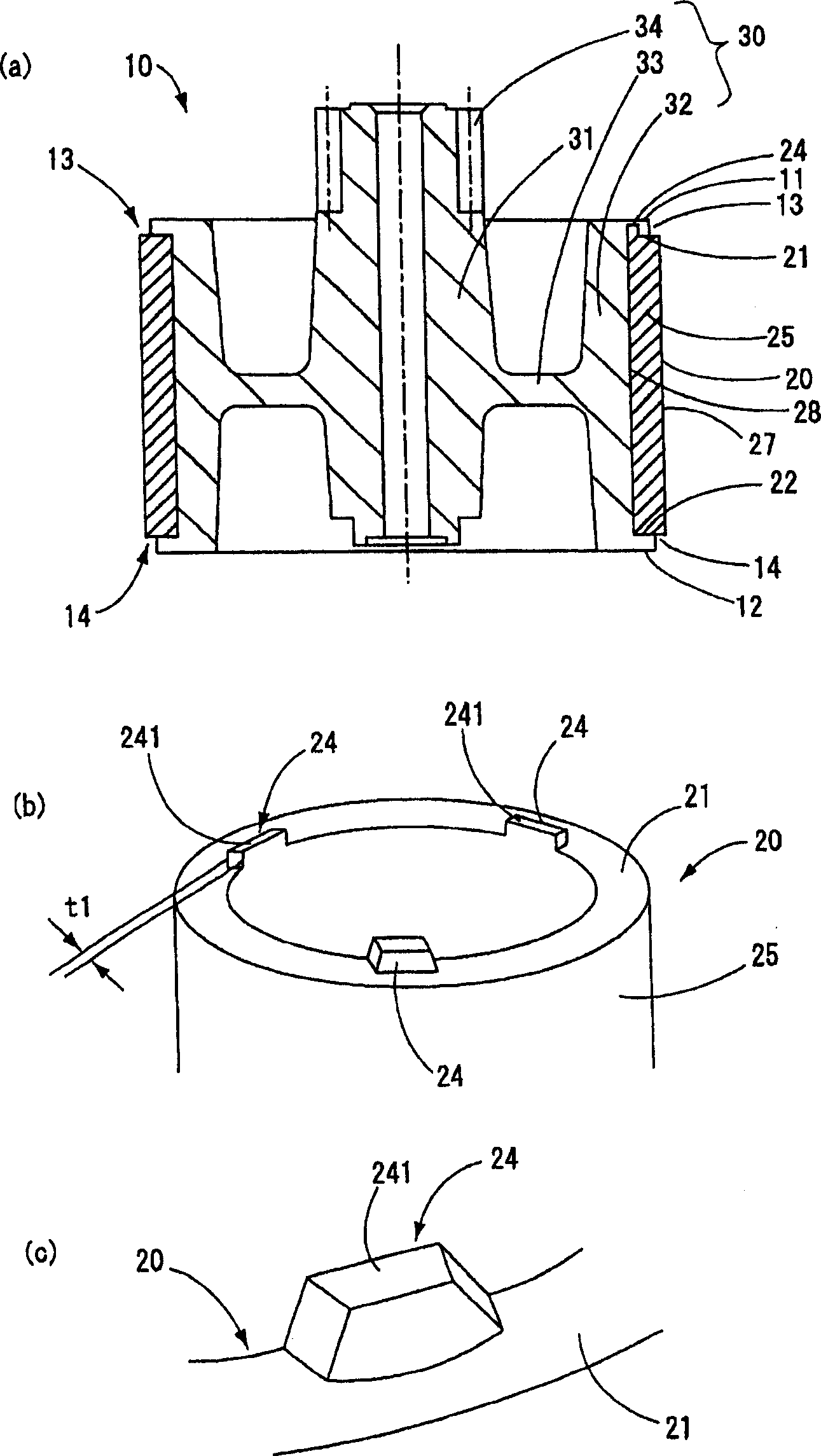
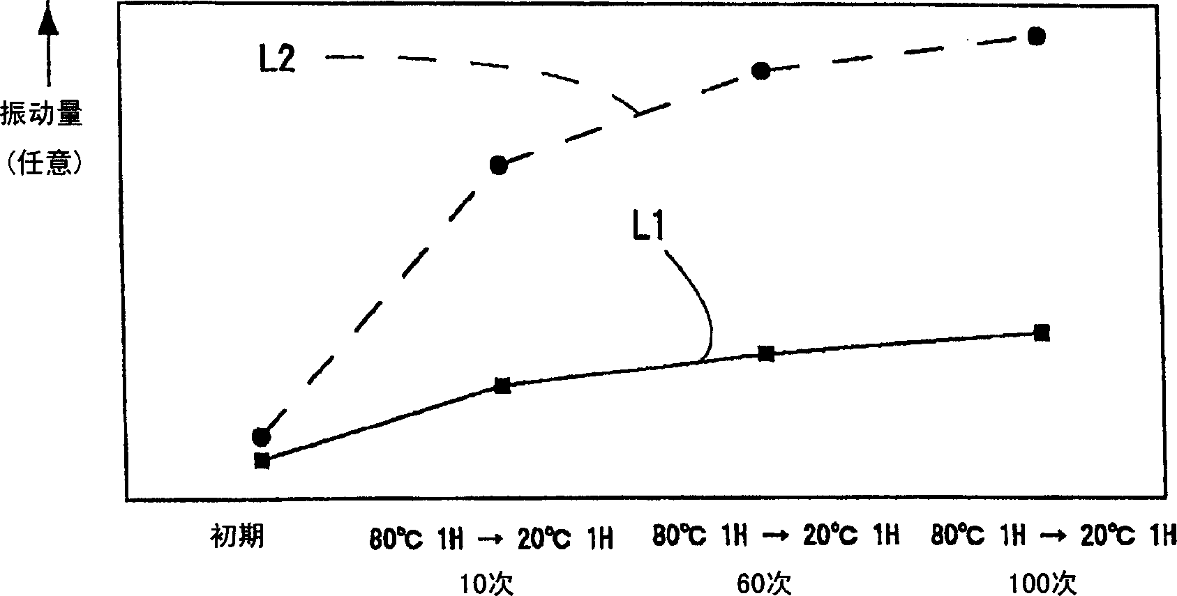
[0032] figure 1It is an explanatory diagram of a geared motor to which the present invention is applied. figure 2 (a), (b), and (c) are respectively a cross-sectional view of the motor rotor according to Embodiment 1 of the present invention, a perspective view showing the upper end portion of a cylindrical magnet used in the motor rotor, and a portion formed on the cylindrical magnet. An enlarged perspective view of the anti-spin protrusion on the upper end. image 3 It is a graph showing changes in the amount of vibration of the rotor when the motor is subjected to a temperature cycle test.

[0033] figure 1 The shown geared motor 1 is used to drive a shutter of an air outlet of an air conditioner, a damper of a water heater, a refrigerator, etc., and has a motor unit 3 and a reduction gear set 4 inside a motor case 2 ...


PUM


Abstract

This invention provides a rotor for a motor and a motor that can improve durability and motor characteristics even when a cylindrical magnet and a resin are integrally formed. In the motor, projections 24 for the prevention of slip are formed on one side end surface 21 of the rotor 20. These projections 24 bite into a resin portion 30. This structure prevents the cylindrical magnet 20 from rotating against the resin portion 30, even if a small gap between the resin potion 30 and the inside circumferential surface 28 of the cylindrical magnet 20 is caused by the shrinkage of the resin portion 30 when a heat cycle test or the like is performed.

Description

(1) Technical field [0001] The present invention relates to a rotor for a motor and a motor having the rotor for a motor. (2) Background technology [0002] In motors in which cylindrical magnets are arranged on the rotor side, a rotor in which either the inner or outer peripheral surfaces of the cylindrical magnets are exposed and integrally molded with the cylindrical magnets and resin (motor rotor) may be used. In this type of motor, the stator is arranged to face the peripheral surface of the rotor on which the cylindrical magnets are exposed (for example, refer to Patent Document 1). [0003] With such a structure, the pinion gear and the cylindrical bearing part in which the support shaft is fitted can be constituted by the resin part. However, when rare earth magnets such as neodymium magnets are used as the cylindrical magnets, since the materials of the magnets are expensive, in order to reduce the cost of the motor, such as Figure 5 As shown in (a) and (b), it is...

Claims


Application Information

Patent Timeline
Patent Type & Authority Applications(China)
IPC IPC(8): H02K1/06H02K1/27
Inventor 伊藤敏朗
Owner SANKYO SEIKI MFG CO LTD
Why Eureka
Try Eureka