
Self-adaptive low-voltage remote power supply device of little smart and its working method

A remote power supply and self-adaptive technology, applied in the field of electronic technology applications, can solve the problems of insufficient utilization of line resources, easy electric shock caused by maintenance personnel, unreasonable power transmission power, etc. The effect of extending the power supply distance

Inactive Publication Date: 2006-10-11
张旭
View PDF0 Cites 1 Cited by
  • Summary
  • Abstract
  • Description
  • Claims
  • Application Information

AI Technical Summary

Problems solved by technology

At present, the PHS power supply is generally powered by high-voltage output power from the central equipment through the remote equipment. The remote power supply and ISDN signal are multiplexed on one line to transmit power and signal separately. Therefore, the line is always in a high-voltage state, and it is easy for maintenance personnel. Cause electric shock, there is a potential safety hazard; the power transmission power is unreasonable, so that the line resources are not fully utilized

Method used


Image

  • Self-adaptive low-voltage remote power supply device of little smart and its working method

Examples


Embodiment

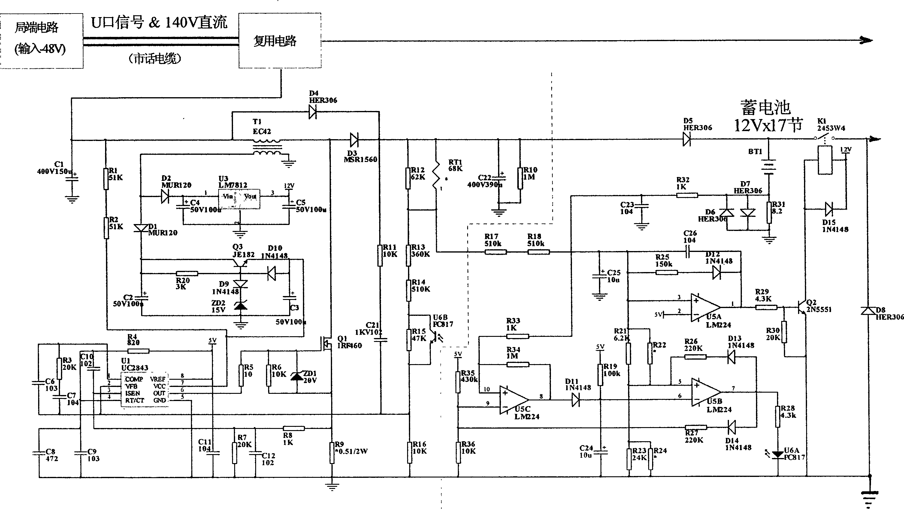
[0020] Embodiment: The electric schematic diagram of the present invention is as shown in the accompanying drawing, comprises accumulator, conversion circuit and control circuit, and conversion circuit is connected with local end circuit through multiplexing circuit, is connected with control circuit through optocoupler simultaneously; Control circuit and accumulator A relay is connected in parallel between the control circuit and the output end of the storage battery; the output end of the storage battery is connected to the PHS base station.

[0021] The conversion circuit is composed of a transformer, a switching power supply controller, a three-terminal voltage stabilizing block, a MOS field effect transistor, a triode, a diode, and resistance and capacitance components. The three-terminal voltage stabilizing block is connected in parallel and connected to the transformer secondary coil through a reverse diode connection, the three-terminal voltage stabilizing block is conn...


PUM


Abstract

The invention comprises an accumulator with output end connected to the base station of little smart wireless city phone, a conversion circuit connected to local side and the control circuit by a multiplexer and a photocoupler respectively, which comprises a transformer, a switch source controller, a tri-end voltage stabilizing block, a MOSFET, a triode, a diode, and resistance and capacitor element; and a control circuit connected to the accumulator, which comprises an operational amplifier, a triode, a diode, and resistance and capacitor element. Wherein, it parallels a relay between the control circuit and the lead-acid accumulator (1.2-2A / h, 12V*17).

Description

1. Technical field [0001] The invention relates to a PHS self-adaptive low-voltage remote power supply device and a working method thereof, belonging to the technical field of electronic technology application. 2. Background technology [0002] PHS is a personal access system that relies on the existing fixed-line network and uses cellular technology to achieve unlimited coverage. The PHS base station is powered by the central equipment through the remote equipment. However, due to the small power of PHS base stations, there are many PHS base stations, so the requirements for power supply equipment of PHS base stations are relatively high. At present, the PHS power supply is generally powered by high-voltage output power from the central equipment through the remote equipment. The remote power supply and ISDN signal are multiplexed on one line to transmit power and signal separately. Therefore, the line is always in a high-voltage state, and it is easy for maintenance person...

Claims


Application Information

Patent Timeline
IPC IPC(8): H04Q1/28H04Q7/30
Inventor 张旭
Owner 张旭
Learn More