Passive channel correcting method based on non-linear antenna array

An antenna array, channel correction technology, applied in the reflection/re-radiation of radio waves, radio wave measurement systems, instruments, etc.

Inactive Publication Date: 2006-10-18
WUHAN UNIV
View PDF1 Cites 14 Cited by
  • Summary
  • Abstract
  • Description
  • Claims
  • Application Information

AI Technical Summary

Problems solved by technology

However, this invention is actually a special active correction method with limited application range and practical effect. It is not suitable

Method used


Image

  • Passive channel correcting method based on non-linear antenna array
  • Passive channel correcting method based on non-linear antenna array
  • Passive channel correcting method based on non-linear antenna array

Examples


Embodiment Construction

[0041] The key point of the present invention is to transform the channel correction problem into a parameter estimation problem by establishing a single-direction echo signal model received by the non-linear antenna array, and thereby obtain a relatively accurate channel mismatch estimation.

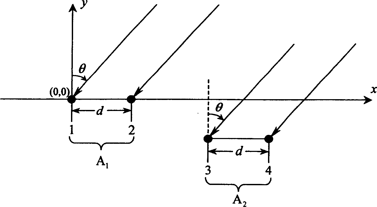
[0042] Think first Figure 4 In the case of an arbitrary nonlinear antenna array with M (M≥3) elements shown, the specific implementation manner of the present invention in this case will be described in steps below.

[0043] (1) Signal model

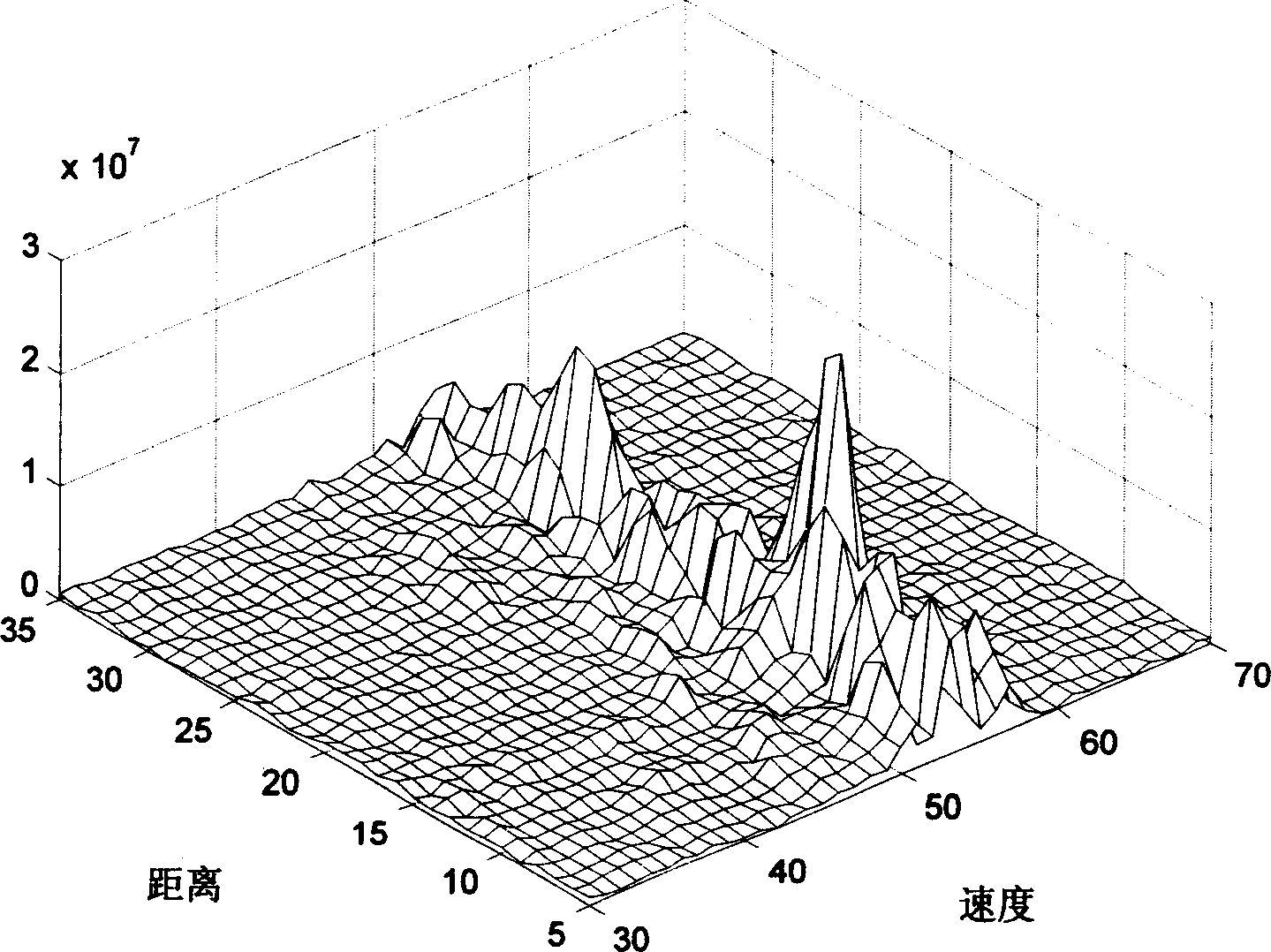
[0044] Assume Figure 4 The element position coordinates of the non-linear antenna array shown are (x i ,y i )(i=1, 2, Λ, M), where element 1 is the coordinate origin, that is (x 1 ,y 1 )=(0,0). The ocean echo can be regarded as a plane wave. Assuming that there are L (L≥3) single-azimuth echoes detected from the range-Doppler (velocity) two-dimensional echo spectrum, the lth (l= 1, 2, Λ, L) single azimuth echo output as

[0045] ...


PUM


Abstract

The passive channel correcting method based on non-linear antenna array includes: configuring the antenna array as non-linear form containing translation invariant array element pairs; detecting single-bearing sea echo with the translation invariant array element pairs; estimating the channel amplitude mismatch ratio with the sea echo to realize amplitude correction; and estimating the channel phase mismatch ratio with the single-bearing sea echo with corrected amplitude and known array position information to realize phase correction. The present invention is one true passive channel correcting method needing no any auxiliary signal source, and has the advantages of no ship echo interference and multipath effect, high precision and robustness, less operation amount, capacity of uninterrupted operation, greatly improved radar application flexibility, raised detection performance, and low cost.

Description

technical field [0001] The invention relates to a method for passive channel correction of high-frequency ground wave radar based on a non-linear antenna array. Background technique [0002] High-frequency ground-wave radar takes advantage of the small attenuation of high-frequency electromagnetic waves on the conductive ocean surface, uses vertically polarized antennas to radiate radio waves, and can detect moving targets such as ships, aircraft, and missiles that appear below the line of sight of sea level beyond the horizon. In addition, high-frequency ground wave radar uses the first-order scattering and second-order scattering mechanisms of the ocean surface for high-frequency electromagnetic waves to extract sea state information such as wind field, wave field, and flow field from radar echoes, which can realize a wide range of marine environment monitoring. , high-precision and all-weather real-time monitoring. [0003] Due to the differences in the hardware itself, ...

Claims


Application Information

Patent Timeline
IPC IPC(8): G01S7/03G01S13/00
Inventor 程丰吴雄斌
Owner WUHAN UNIV
Why Eureka
Try Eureka