
Micro-displacement driver with non-linear correcting function

A driver and micro-displacement technology, applied in the field of drivers, can solve the problems of unpredictability, hysteresis effect of piezoelectric actuator output displacement, low positioning accuracy of micro-displacement actuator, etc., and achieve the effect of facilitating micro-displacement control and improving micro-displacement accuracy.

Inactive Publication Date: 2006-10-25
梁宜勇
View PDF0 Cites 1 Cited by
  • Summary
  • Abstract
  • Description
  • Claims
  • Application Information

AI Technical Summary

Problems solved by technology

At present, in order to reduce the volume of the micro-displacement system, improve its compactness, reduce the complexity of its structure and control, and improve the convenience of its use, the micro-displacement system is designed to work in an open-loop state, that is, in the micro-displacement system There is no additional displacement detection equipment (such as grating ruler, laser rangefinder, capacitance micrometer, inductance micrometer, etc.) to monitor the actual displacement of the micro-displacement actuator, so the positioning accuracy of the micro-displacement actuator is very low , especially when the output displacement of the micro-displacement actuator and the input electrical signal (voltage or current) are nonlinear, the displacement cannot be accurately predicted, so that it can only be processed approximately linearly, thereby reducing the positioning accuracy of the micro-displacement system, such as causing The image distortion of the atomic force microscope, the surface shape distortion measured by the digital wave surface interferometer, and the dimensional accuracy of the CNC machine tool parts are only in the order of 1-5 μm, which cannot meet the ultra-precision processing requirements of 0.1 μm and surface roughness Ra less than 0.025 μm. Unable to achieve sub-micron / nano precision control in optical fiber, semiconductor, precision machinery manufacturing industries, intelligent machining, tool manufacturing and other industries
[0003] Although voltage-driven piezoelectric micro-displacement actuators are widely used today, although they have high resolution, fast response, and large thrust, their voltage-displacement characteristic curve is hysteretic and nonlinear. When driven by a linear voltage, the output displacement is nonlinear. , if the driving voltage changes randomly back and forth, the output displacement of the piezoelectric actuator is even more difficult to predict due to the hysteresis effect

Method used


Image

  • Micro-displacement driver with non-linear correcting function
  • Micro-displacement driver with non-linear correcting function

Examples


Embodiment

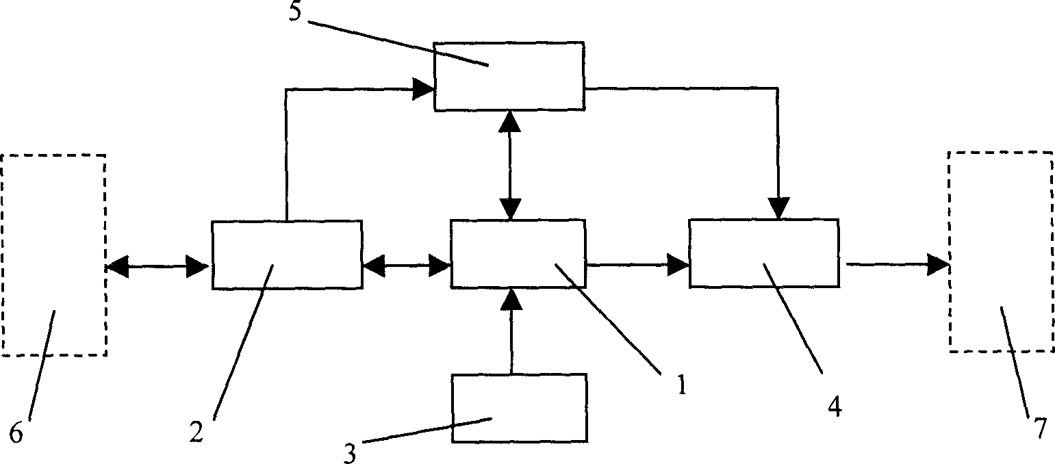
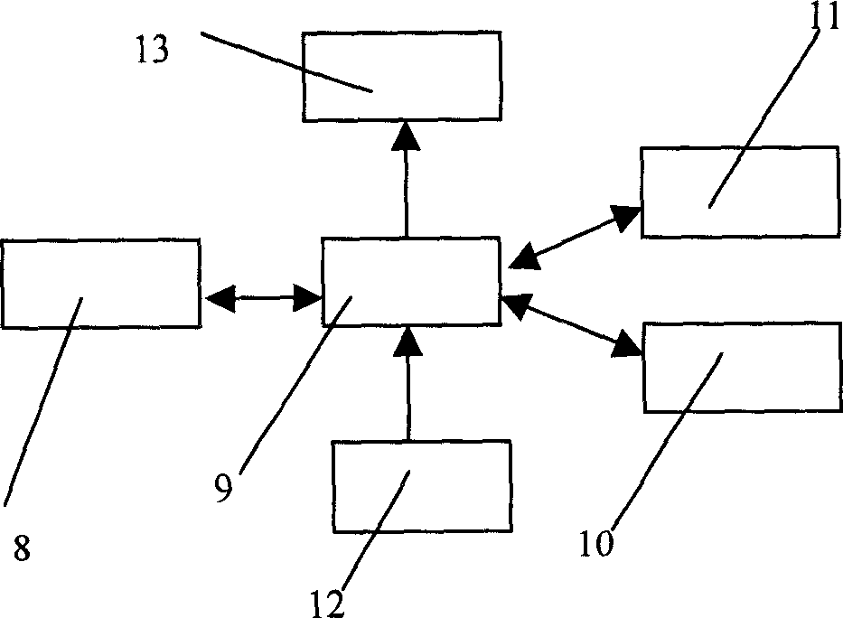
[0018] See attached figure 1 , 2 : The application object of the driver of the present invention is a micro-displacement actuator with nonlinear voltage-displacement characteristics, such as a common piezoelectric micro-displacement device. Using the driver of the present invention through two stages, the first is the calibration stage, the driver of the present invention (under the control of its internal intelligent core) scans the characteristic parameters of the external micro-displacement actuator, and then the intelligent core in the driver performs a The external actuator establishes a mathematical model; the second is the actual working stage. In the working stage, the driver outputs a certain voltage to drive the external actuator according to the displacement command sent by the PC, combined with the mathematical model of the actuator. Make the external actuator output the displacement consistent with the PC machine command. The implementation process of the two ph...


PUM


Abstract

The invention relates to a driver to drive micro displacement actuator that is made up of intelligent core, USB interface, displacement analog input interface, drive output interface, and invert / driving module. After the displacement instruction being inputted into PC, the displacement output could be executed and the accuracty could be nanometer / micrometer extent.

Description

technical field [0001] The invention relates to a driver for driving a micro-displacement actuator to generate displacement. In particular, it is a driver for displacement actuators whose displacement accuracy is on the order of nanometers / micrometers, driven by voltage, and whose voltage-displacement characteristics have nonlinear characteristics. Background technique [0002] Many devices in the field of precision engineering, such as autofocus microscopes, atomic force microscopes, digital wave surface interferometers, medical micromanipulators, optical fiber docking mechanisms, and CNC machine tools, are equipped with micro-displacement actuators for controlling lenses, probes, and workpieces. The displacement of the micro-displacement actuator must be known and controllable. At present, in order to reduce the volume of the micro-displacement system, improve its compactness, reduce the complexity of its structure and control, and improve the convenience of its use, the ...

Claims


Application Information

Patent Timeline
IPC IPC(8): G01B21/02
Inventor 梁宜勇顾智企孙戎潘宏高黄腾超
Owner 梁宜勇
Features
  • Generate Ideas
  • Intellectual Property
  • Life Sciences
  • Materials
  • Tech Scout
  • Unparalleled Data Quality
  • Higher Quality Content
  • 60% Fewer Hallucinations
Learn More