Circuit using dielectric unit capacitor

A dielectric and capacitor technology, applied in the field of capacitors, can solve problems such as oxide layer collapse, and achieve the effects of low gate leakage current, high unit capacitance value, and high reliability

Inactive Publication Date: 2006-10-25
TAIWAN SEMICON MFG CO LTD
View PDF0 Cites 4 Cited by
  • Summary
  • Abstract
  • Description
  • Claims
  • Application Information

AI Technical Summary

Problems solved by technology

And when the thin dielectric capacitor is close to the I / O pad, the phenomenon of electrostatic discharge (ESD) is more likely to cause the collapse of the oxide layer

Method used


Image

  • Circuit using dielectric unit capacitor
  • Circuit using dielectric unit capacitor
  • Circuit using dielectric unit capacitor

Examples


Embodiment Construction

[0031] In order to make the above-mentioned and other objects, features and advantages of the present invention more comprehensible, the preferred embodiments are listed below, together with the accompanying drawings, and are described in detail as follows:

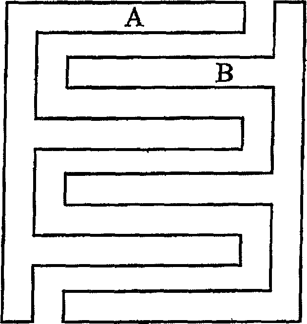
[0032] The technique of stacking thin dielectric capacitors will be described in detail below. When the stacked thin dielectric capacitor has a high unit capacitance, it can still achieve high reliability of the gate oxide layer and low leakage current characteristics. The response time of the thin dielectric capacitor can be set by adjusting the poly width of the thin dielectric capacitor. Each unit capacitor includes at least two thin dielectric capacitors connected in series. The invention is particularly evident for high density ICs in which the gate dielectric thickness of the capacitors is less than 50 Ȧ and the active transistors have a minimum gate width of about 0.18 μm or smaller.

[0033] Figure 2a An equi...


PUM


Abstract

This invention relates to a circuit using a thin dielectric unit condenser including one or more than one circuit modules and one or more than one decoupling modules coupled to said circuit modules, in which, every decoupling module has one or more decoupling thin dielectric unit condensers including: a first node coupled to a first circuit connecting point of the circuit module, a second node coupled to a second circuit connecting point of the circuit module and two or more thin dielectric condensers connected between the two nodes in series and at least the thickness of a grid dielectric of a thin dielectric condenser is less than 50.

Description

technical field [0001] The present invention relates to a capacitor for an integrated circuit, and more particularly to an integrated circuit having a stacking thin dielectric decoupling capacitor with high unit capacitance. Background technique [0002] In a general semiconductor chip structure, logic gates in an integrated circuit (hereinafter referred to as IC) are coupled to power lines and ground lines. When the power supply provides power to the IC, the current will flow through the power line, logic components, and flow to the ground line. When logic elements switch, the current changes dramatically over a small period of time. The decoupling capacitor can be used to withstand the interference caused by the above-mentioned current change, and maintain the voltage between the power supply and the ground at a constant value. A good decoupling capacitor has low leakage current, short time constant, and high capacitance per unit area. It is generally known that the dec...

Claims


Application Information

Patent Timeline
Patent Type & Authority Applications(China)
IPC IPC(8): H01L27/02
Inventor 庄建祥
Owner TAIWAN SEMICON MFG CO LTD
Why Eureka
Try Eureka