
Thermal interface material and its production

A technology of thermal interface materials and nanocomposite materials, which is applied in heat exchange materials, chemical instruments and methods, etc., can solve the problems of poor thermal conductivity of thermal interface materials, insufficient thermal conductivity, and inability to meet the needs of heat dissipation performance, etc. Excellent thermal conductivity, the effect of improving thermal conductivity

Inactive Publication Date: 2006-11-01
HONG FU JIN PRECISION IND (SHENZHEN) CO LTD +1
View PDF0 Cites 14 Cited by
  • Summary
  • Abstract
  • Description
  • Claims
  • Application Information

AI Technical Summary

Problems solved by technology

[0004] However, the thermal conductivity of the above-mentioned metal or ceramic particle fillers is still not high enough (for example, the thermal conductivity of metallic silver is 428W / K m), so the overall thermal conductivity of the thermal interface material is poor, and it cannot adapt to the high integration and high performance of semiconductors. Cooling Performance Requirements

Method used


Image

  • Thermal interface material and its production
  • Thermal interface material and its production
  • Thermal interface material and its production

Examples


Embodiment Construction

[0028] The present embodiment will be further described in detail below in conjunction with the accompanying drawings.

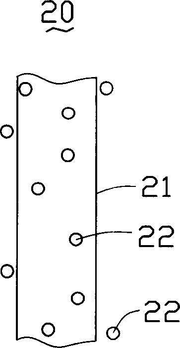
[0029] See figure 1 and figure 2 , figure 1 is a schematic structural view of the nanocomposite material 20 in this embodiment, figure 2 It is a schematic diagram of the composition of the thermal interface material 1 in this embodiment. The first embodiment of the present invention provides a thermal interface material 1 , which includes a matrix 10 and nanocomposite materials 20 distributed in the matrix 10 . Wherein, the nanocomposite material 20 includes nanofibers 21 and heat conducting particles 22 distributed inside and outside the nanofibers 21 .

[0030] The material of the substrate 10 can be selected from polymer materials such as silica gel, polysiloxane resin, epoxy resin, polyester, polyester oil, polyurethane, polyimide or polyacrylic acid. The nanofibers 21 can be selected from fiber materials such as carbon nanotubes, carbon nanowires...


PUM

PropertyMeasurementUnit
particle diameteraaaaaaaaaa

Abstract

The invention includes a kind of hot interface material and the method of preparing it. This kind of hot interface material contains parent materials and nanocrystalline composite materials in the base stock. The nanocrystalline composite materials includes nanometer fiber and heat-conducting granules which disperse inside the nanometer fiber pipe and outside.This nanometer fiber comes from carbon nanometer pipe, carbon nanometer line or carbon fiber. The size of heat-conducting granules can be micron level, but the nanometer level is better. This invention also provides the method of preparing the hot interface material.

Description

【Technical field】 [0001] The invention relates to a heat interface material and a preparation method thereof, in particular to a heat interface material utilizing nanometer materials and a preparation method thereof. 【Background technique】 [0002] In recent years, with the rapid development of the integration process of semiconductor devices, the degree of integration of semiconductor devices has become higher and higher, and the volume of devices has become smaller and smaller; its heat dissipation has become an increasingly important issue, and its requirements for heat dissipation have also become more and more important. Higher and higher. In order to meet the heat dissipation requirements of the device, various heat dissipation methods are widely used, such as fan heat dissipation, water-cooled auxiliary heat dissipation, and heat pipe heat dissipation, etc., and a certain heat dissipation effect has been achieved. However, since the contact interface between the heat...

Claims


Application Information

Patent Timeline
Patent Type & Authority Applications(China)
IPC IPC(8): C09K5/14
Inventor 董才士
Owner HONG FU JIN PRECISION IND (SHENZHEN) CO LTD
Learn More