
Wireless-line-shared network system, and management apparatus and method therefor

A technology for sharing a network and a management device, applied in the field of mobile communication network systems, can solve the problems that communication operators cannot afford the cost, service expansion delay, etc., and achieve the effect of effective sharing and flexible sharing

Inactive Publication Date: 2006-11-08
NEC CORP
View PDF1 Cites 7 Cited by
  • Summary
  • Abstract
  • Description
  • Claims
  • Application Information

AI Technical Summary

Problems solved by technology

Therefore, communication operators cannot afford the cost of the next capital investment, which causes business expansion to be delayed

Method used


Image

  • Wireless-line-shared network system, and management apparatus and method therefor
  • Wireless-line-shared network system, and management apparatus and method therefor
  • Wireless-line-shared network system, and management apparatus and method therefor

Examples


no. 1 example

[0045] 1. System configuration

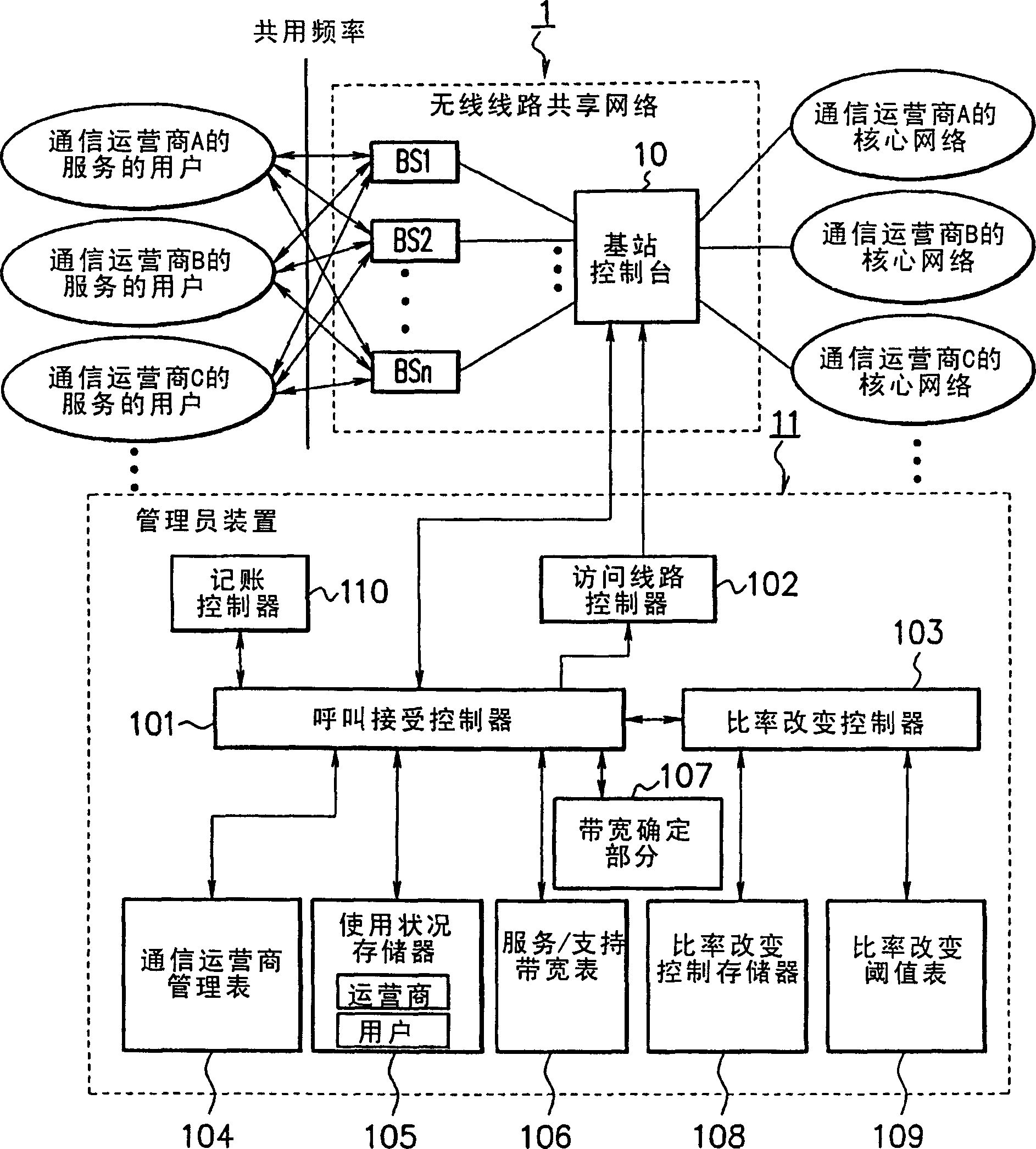
[0046] figure 2 is a block diagram showing the configuration of the wireless line sharing network system according to the first embodiment of the present invention. The wireless line sharing network 1 includes a plurality of wireless base stations BS1 to BSn, wireless facilities such as a base station console 10, and wired facilities such as wired cables and routers (not shown). The base station console 10 controls the wireless base stations BS1 to BSn to transfer control signals or data between the base stations BS1 to BSn and the core network of the communication carrier. The base station console 10 is controlled by an administrator device 11 as will be described below.

[0047] As is generally known, radio base stations BS1 to BSn are geographically distributed. Each radio base station creates or covers a radio zone (cell) using a designated shared frequency and is capable of communicating with a plurality of user terminals (hereinafter ...

no. 2 example

[0103] Figure 12 is a block diagram showing the configuration of a wireless line sharing network system according to a second embodiment of the present invention. In the wireless line sharing network system of this embodiment, the base station console 10 is connected to the local server of each communication carrier and the core network of the communication carrier. In this embodiment, the radio bandwidth allocation pattern in the priority bandwidth guarantee system is set in the communication carrier management table 104, and the administrator device 11 for controlling the Coordination between communication carriers lending idle bandwidth. In other respects, the system is configured like figure 2 The configuration of the first embodiment is shown, and similar reference numerals are used in designating corresponding parts, and a detailed description thereof will not be repeated.

[0104] Figure 13 is a flowchart of an example of the coordination operation of the coordinat...


PUM


Abstract

A wireless-line-shared network system capable of charging in accordance with use of a wireless communication network so as to reduce the investment costs of communication providers. The user terminals of the communication providers use radio frequencies, which are permitted by authorities, to connect with the corresponding communication provider networks via radio base stations (BS) and a controlstation (10). In response to call connection requests, a call acceptance control part (101) performs call acceptances and band managements based on wireless band allocation patterns, which established by subscriptions, and based on current use statuses. A bandwidth decision part (107) decides bandwidths for the call connection requests by use of the call connection requests, call connection responses and a bandwidth table (106). A rate change control part (103) adjusts the bandwidths of the user terminals such that the currently used bandwidths of the communication providers are kept within predetermined ranges. A charge control part (110) charges the communication providers in accordance with their wireless band rental subscriptions.

Description

technical field [0001] The present invention relates to a mobile communication network system using licensed radio frequencies, and more particularly, to a technique for sharing a system by a plurality of communication carriers. Background technique [0002] In recent years, there has been an increasing demand for high-speed data communication compatible with mobile multimedia services and a system that can be shared by all mobile terminals of a certain type spread all over the world. Faced with this situation, global standards for mobile communication systems have been defined, and development of the systems has been promoted. Therefore, IMT-2000 systems such as WCDMA systems have been introduced. [0003] Such as Figure 1B As shown, a network system typified by WCDMA is a line occupation type system in which each communication carrier or provider acquires a licensed frequency and builds and manages wireless and wired facilities. In general, such line-occupied systems re...

Claims


Application Information

Patent Timeline
Patent Type & Authority Applications(China)
IPC IPC(8): H04W4/24H04W28/20H04W28/22H04W72/04
CPCH04M15/51H04M15/81H04M2215/0112H04M2215/32H04M2215/54H04W4/24H04W28/20H04W28/22H04W28/26H04W72/0453H04W76/10
Inventor 菊地庸之
Owner NEC CORP
Learn More