Oil cooling compressor

A compressor and oil-cooled technology, applied in the direction of liquid variable capacity machinery, mechanical equipment, variable capacity pump components, etc., can solve the problems of not being able to reduce the temperature of the oil supply, and the performance of the compressor.

Active Publication Date: 2006-11-15
코벨코컴프레서가부시키가이샤
View PDF2 Cites 29 Cited by
  • Summary
  • Abstract
  • Description
  • Claims
  • Application Information

AI Technical Summary

Problems solved by technology

Therefore, in order to prevent moisture condensation only by temperature control, it is necessary to estimate the discharge pressure in the state where the gas pressure is the highest and perform temperature control. As a result, the oil supply temperature cannot be lowered.
That is, it is very important to maintain the discharge temperature at an appropriate temperature. If the control is only based on the oil supply temp

Method used


Image

  • Oil cooling compressor
  • Oil cooling compressor
  • Oil cooling compressor

Examples


Embodiment Construction

[0018] One embodiment of the present invention will be described below with reference to the drawings.

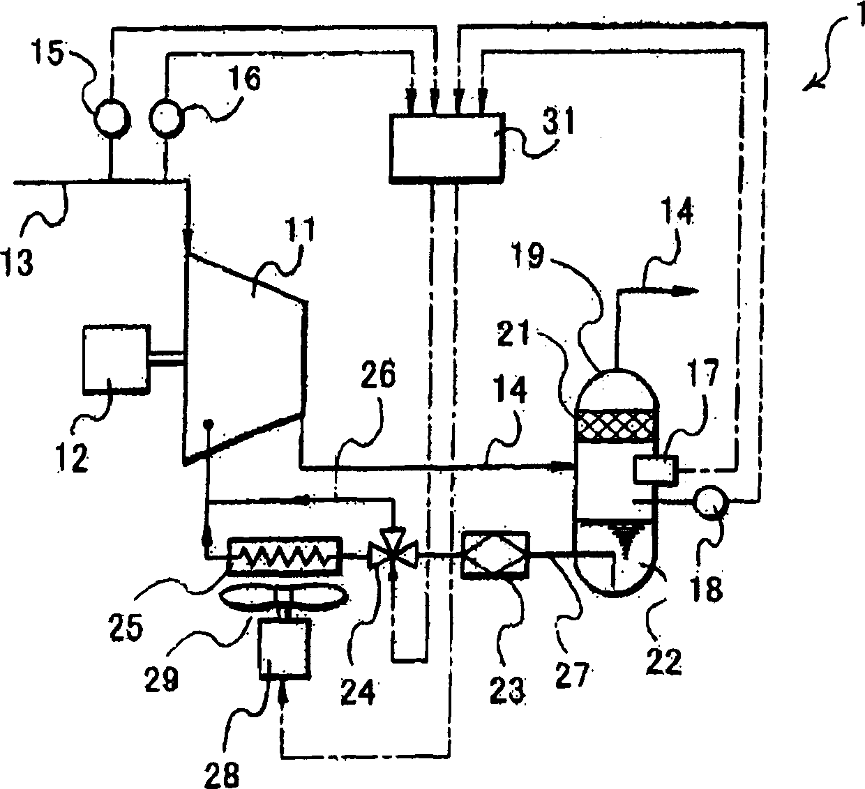
[0019] figure 1 An oil-cooled compressor 1 according to the present invention is shown. A compressor main body 11 of the oil-cooled compressor 1 uses a motor 12 as a drive unit and is connected to a suction flow path 13 and a discharge flow path 14 .

[0020] The suction flow path 13 is provided with a suction temperature detector 15 for detecting the temperature of the suction gas and a suction humidity detector 16 for detecting the humidity of the suction gas, and an oil separator 19 is provided on the discharge flow path 14 . In addition, an oil separation element 21 is provided in the upper part of the oil separation and recovery device 19 , and an oil storage part 22 is provided in the lower part of the oil separation and recovery device 19 .

[0021] In addition, in the space between the oil separation element 21 and the oil storage part 22 of the oil separation and ...


PUM


Abstract

The oil-cooled compressor is equipped with an oil flow path, a discharge temperature detector and a control device. The oil flow path starts from the oil storage part of the oil separator and recovers to the temperature regulating valve with a two-way variable diversion function, and passes through the cooling After the air-cooled oil cooler supplied by the fan, or after passing through the bypass flow path instead of the air-cooled oil cooler, it leads to the above-mentioned gas compression space, and the oil separation and recovery device compresses the gas supplied to the main body of the compressor The oil behind the space is separated and recovered from the discharge gas; the discharge temperature detector detects the discharge temperature of the gas; the control device controls the cooling fan motor and the temperature regulating valve based on the discharge temperature detected by the discharge temperature detector to Adjust the speed of the motor and the split ratio of the temperature regulating valve. The oil-cooled compressor can prevent condensation and precipitation of moisture in the discharge gas, and can save energy.

Description

technical field [0001] The present invention relates to an oil-cooled compressor equipped with an air-cooled oil cooler. Background technique [0002] Conventionally, an oil-cooled compressor equipped with an air-cooled oil cooler is known (for example, refer to JP-A-6-213186 and JP-A-2003-206864). [0003] JP-A-6-213186 discloses an oil-cooled compressor that detects the oil temperature at the outlet of an air-cooled oil cooler, controls the air volume for cooling the oil-cooled cooler based on the detected temperature, and maintains The temperature of the oil entering the compression main body is at the set temperature, thereby suppressing the condensation of the moisture (drain) in the oil. [0004] Japanese Patent Application Laid-Open No. 2003-206864 discloses an oil-cooled compressor that controls the rotation speed of the motor, which is the driving part of the cooling fan of the air-cooled oil cooler, based on the detected discharge temperature, and maintains the di...

Claims


Application Information

Patent Timeline
IPC IPC(8): F04B39/06F04B27/00
Inventor 中村元
Owner 코벨코컴프레서가부시키가이샤
Why Eureka
Try Eureka