Checking device of the gear-driving balancer

A technology of gear drive and inspection device, which is applied in the direction of machine gear/transmission mechanism testing, etc. It can solve the problems of undetectable gear abnormality, deviation of detection results, long working time, etc.

Inactive Publication Date: 2006-11-15
MAZDA MOTOR CORP
View PDF1 Cites 8 Cited by
  • Summary
  • Abstract
  • Description
  • Claims
  • Application Information

AI Technical Summary

Problems solved by technology

[0004] The technology disclosed in the above-mentioned Patent Document 1 cannot inspect the entire tooth surface because the rotation of any one of the crankshaft gear and the balance gear is restricted.
Therefore, it is impossible to detect the abnormality of the phase of the gear that is staggered from the inspection position
In addition, because the inspection is manual work, the work time is long, and the test results may also be biased

Method used


Image

  • Checking device of the gear-driving balancer
  • Checking device of the gear-driving balancer
  • Checking device of the gear-driving balancer

Examples


Embodiment Construction

[0039] Hereinafter, the best mode for carrying out the present invention will be described with reference to the drawings.

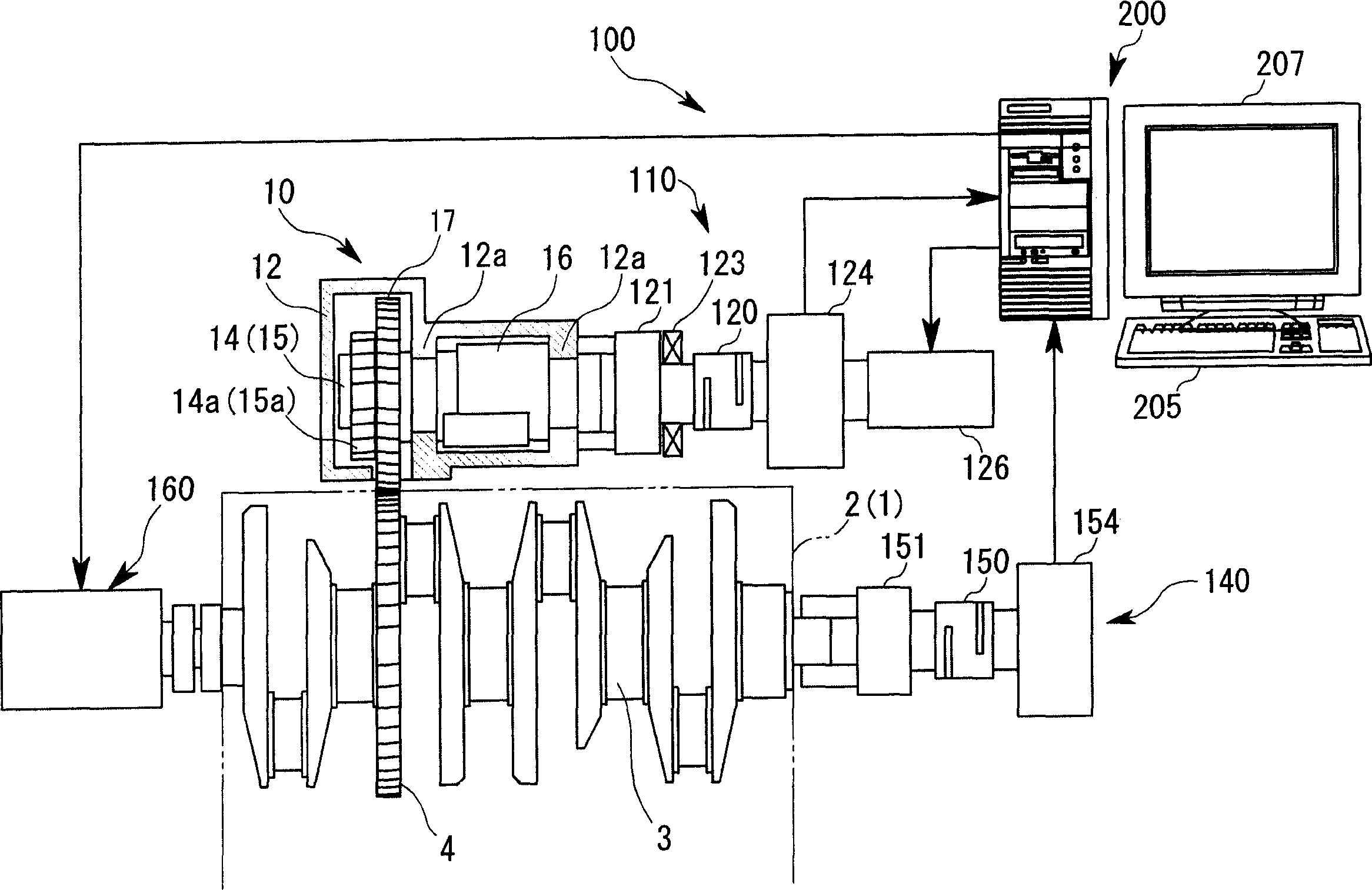
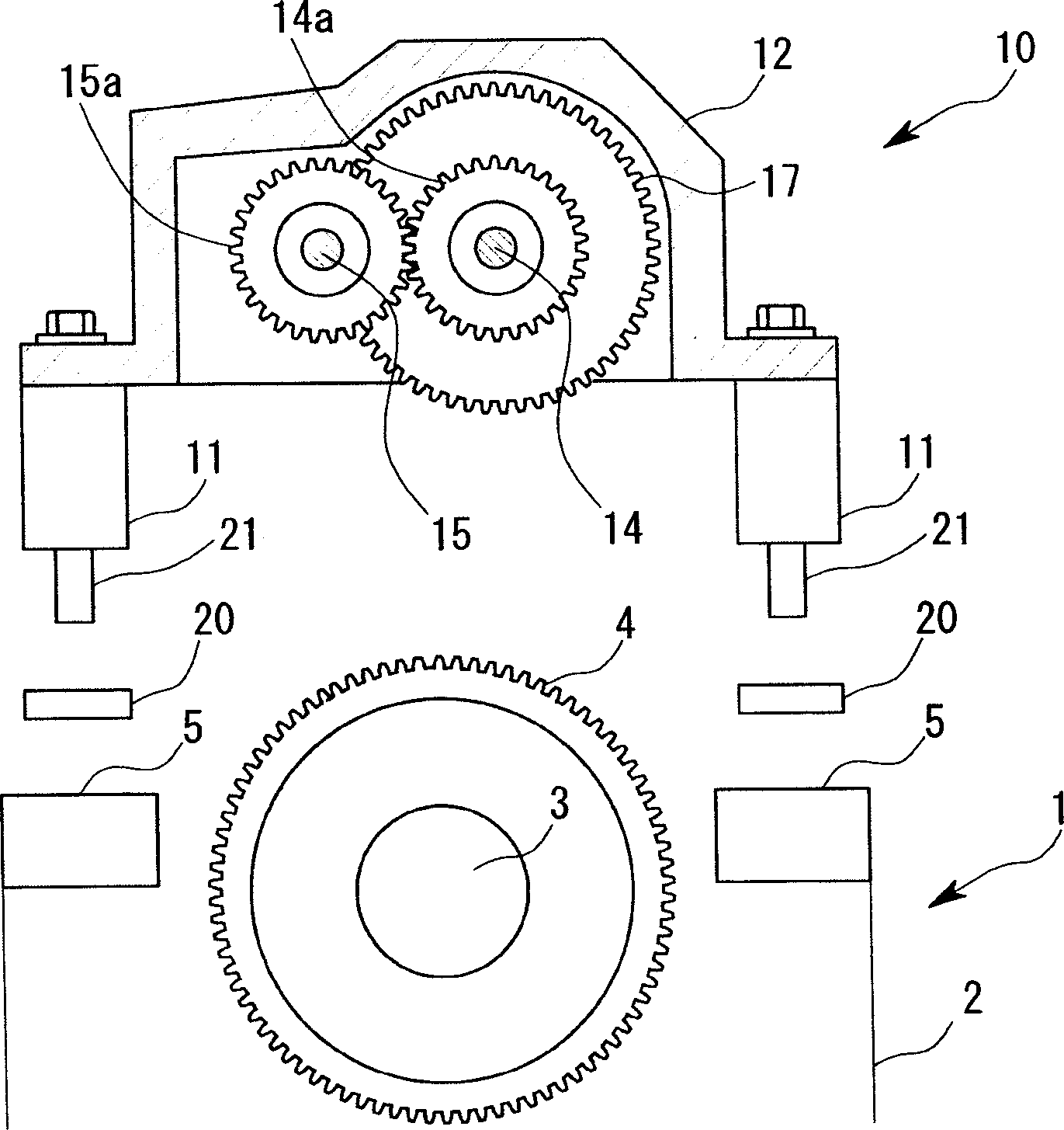
[0040] figure 1 is a structural diagram schematically showing the structure of one embodiment of the present invention, figure 2 is roughly figure 1 A schematic diagram of the installed state of the balancer box 10 and the engine 1.

[0041] refer to figure 1 with figure 2 , the balancer box 10 as the inspection object includes, has 4 cylinders 11 ( figure 2 Only two of them are shown in the figure) housing 12; a pair of balance shafts 14, 15 that are rotatably supported in the housing 12. Each of the balance shafts 14, 15 passes through a pair of bearings 12a formed on the casing 12 (only in the figure 1 shown in the middle) to be supported freely in rotation. Transmission gears 14a, 15a are fixed on the balance shafts 14, 15, and the balance shafts 14, 15 rotate at a rotation ratio of 1:1 through the engagement of the transmission gears 14a, ...


PUM


Abstract

The inspection device of the gear-driven balancer of the present invention includes a driving mechanism (160) that rotates the crankshaft (3); an meshing adjustment mechanism (126) that adjusts the meshing between the balance gear (17) and the crankshaft gear (4). The adjustment mechanism (126) can be adjusted selectively in the driven direction and the anti-driven direction driven by the crank gear (4); the rotation angle detecting device ( 124), (154); detect the axial displacement detecting device (123) that balance shaft (14) moves axially; To above-mentioned driven direction, only adjust balance gear (17) and crankshaft gear (4) with prescribed number of rotations After meshing, switch to the anti-driven direction, and calculate the balance gear (17) and the crankshaft gear (4 ) computing device for backlash. With the present invention, the meshing state of the crankshaft gear and the balance gear can be quickly and accurately detected for the entire tooth surface.

Description

technical field [0001] The invention relates to an inspection device for a gear-driven balancer. Background technique [0002] A conventionally known 4-cylinder engine is provided with a balance shaft having an unbalanced mass that balances the inertial force caused by the reciprocating inertial mass of the piston, connecting rod, etc., and the balance shaft rotates twice for every rotation of the crankshaft. Thereby, the vibration and noise of the connecting rod or the like caused by the above imbalance can be eliminated (for example, Japanese Patent Document 1: Japanese Patent Publication No. 2876819). In order to realize the power transmission between the balance shaft and the connecting rod, a crank gear is shrink fit on the crankshaft, and a balance gear meshing with the crank gear is arranged on the balance shaft. [0003] However, if the back lash between the crankshaft gear and the balance gear is improperly set, there will be gear bumping ...

Claims


Application Information

Patent Timeline
Patent Type & Authority Applications(China)
IPC IPC(8): G01M13/02
Inventor 山口郁夫古谷树启
Owner MAZDA MOTOR CORP
Why Eureka
Try Eureka