Bipolar permanent magnet

A permanent magnet and magnet technology, applied to magnetic objects, permanent magnets, magnetic materials, etc., can solve the problem of not meeting the requirements of the magnetic field, and achieve the effect of strong anti-demagnetization ability, easy production and installation, and light weight

Inactive Publication Date: 2011-06-08
INST OF ELECTRICAL ENG CHINESE ACAD OF SCI
View PDF3 Cites 2 Cited by
  • Summary
  • Abstract
  • Description
  • Claims
  • Application Information

AI Technical Summary

Problems solved by technology

Although the permanent magnet mechanism with this structure can generate a strong magnetic field of 1T to 4T, the polarity of the strong magnetic field changes along the circumferential direction, which cannot meet the requirements of the above-mentioned device for the magnetic field

Method used


Image

  • Bipolar permanent magnet
  • Bipolar permanent magnet
  • Bipolar permanent magnet

Examples


Embodiment Construction

[0018] The present invention will be further described below in conjunction with specific embodiments and accompanying drawings.

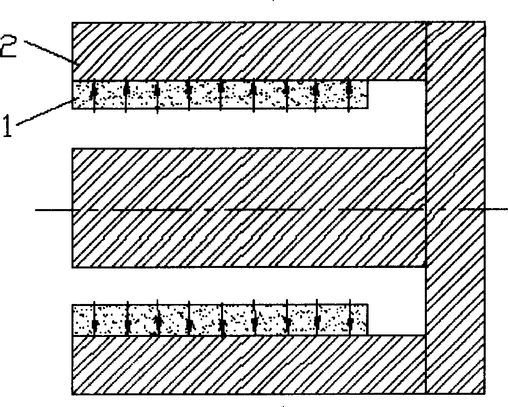
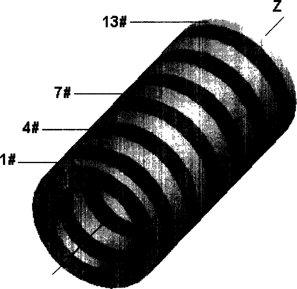
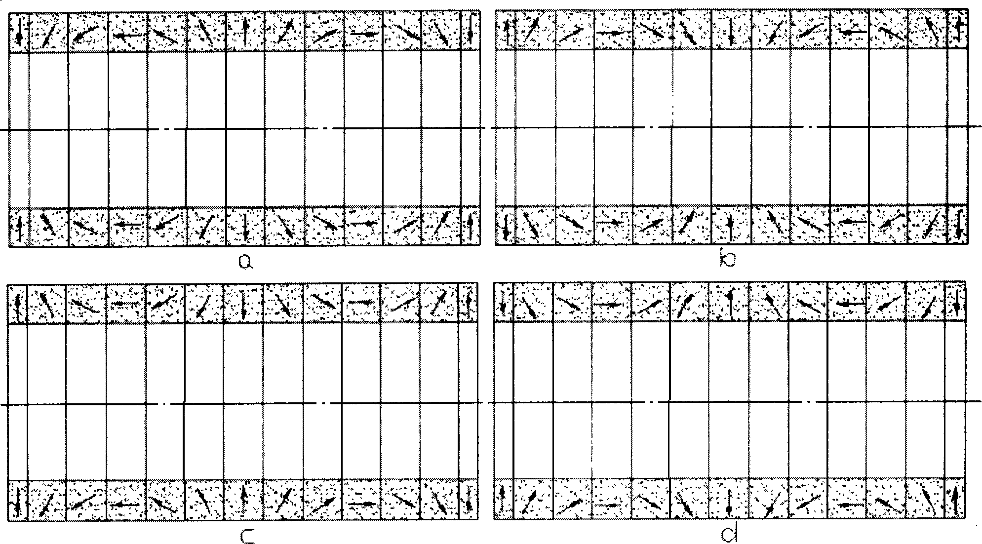
[0019] figure 2 It is a structural diagram of one of the specific embodiments of the present invention. It consists of 13 (n=6) NdFeB magnetic rings with equal radial thickness, and the magnetization directions of adjacent magnetic rings differ by 360° / 2n=30° (n=6). The magnetic circuit structure that can be taken is as image 3 As shown, where a, b are internal magnetic circuit structures, c, d are external magnetic circuit structures. image 3 In a, the magnetization direction of the No. 1 magnetic ring, that is, the leftmost magnetic ring is -90°. From left to right, the magnetization direction of each magnetic ring changes clockwise at 30° until the No. 13 magnetic ring, the 13th The magnetization direction of the magnetic ring is The working space of the magnetic field is the air gap inside the magnet; image 3 In c, the magnetization d...


PUM

PropertyMeasurementUnit
lengthaaaaaaaaaa
lengthaaaaaaaaaa
lengthaaaaaaaaaa

Abstract

This invention relates to antipole permanent magnet, it consists of 2n+1 neodymium iron boron magnetic loop axial overlay. Geometry and magnetization direction of each loop are axial symmetry, their magnetization direction change along certain rule. The adjoint loop magnetization directions are 360 degrees per 2n different look from any axial cross section. Inner or outer air gap is magnetic workspace according to the different magnetic circuit. The 2n+1 loop are fixed by nonmagnetic metal inner and outer shells. There is no ferromagnetic part in the magnetic circuit, series structure is used, and the whole magnetic potential is the stacking of potentials provided by each loop. This invention can generate strong magnetic field with unchanging polar along circle direction. Its structure is simple, it's manufacturing and installation is simple. There is no ferromagnetic part, its weight is light. There is nearly no flux leakage, the anti demagnetizing action ability is strong, its adjustability is good.

Description

technical field [0001] The invention relates to a permanent magnet, in particular to a strong magnetic field opposite pole permanent magnet. technical background [0002] According to the theory of electromagnetic field, when a constant conducting coil passes a current in the circumferential direction, it will be subjected to an axial electromagnetic force under the action of a radial magnetic field. This principle is applied to high-thrust propulsion devices. In a "superconducting electromagnetic piston pump-jet propeller" disclosed in Chinese patent 02155351.3, the antipolar superconducting magnet composed of two sets of superconducting solenoid coils arranged coaxially and symmetrically generates a strong force with constant polarity along the circumferential direction. Magnetic field, and use its radial magnetic field component to interact with the current in the circumferential direction of the constant conduction coil to generate axial electromagnetic thrust. Althoug...

Claims


Application Information

Patent Timeline
Patent Type & Authority Patents(China)
IPC IPC(8): H01F1/057H01F7/02
Inventor 彭燕赵凌志凌金福沙次文李然
Owner INST OF ELECTRICAL ENG CHINESE ACAD OF SCI
Why Eureka
Try Eureka