Ceramic generator

A generator and ceramic technology, applied in induction generators, electrical components, electromechanical devices, etc., can solve the problems of complex structure, small power generation, and difficult realization, and achieve the effect of reducing volume and increasing capacitance

Inactive Publication Date: 2006-11-15
冯连阶
View PDF0 Cites 2 Cited by
  • Summary
  • Abstract
  • Description
  • Claims
  • Application Information

AI Technical Summary

Problems solved by technology

[0002] Existing power generation devices are mainly electromagnetic induction generators. Due to the need for coils and magnetically conductive materials, the structure is complex, the volume is large, the weight is heavy, and it is easy to generate heat during the working process. It must be properly cooled, and the general efficiency is limited to a certain extent.
[0003] Many forms of variable capacitance generators have been proposed, and generally there are defects such as unreasonable structure of linear motion, small power generation, and difficulty in realization.

Method used


Image

  • Ceramic generator
  • Ceramic generator
  • Ceramic generator

Examples


Embodiment Construction

[0021] In order to further illustrate the present invention, below in conjunction with embodiment is described in more detail.

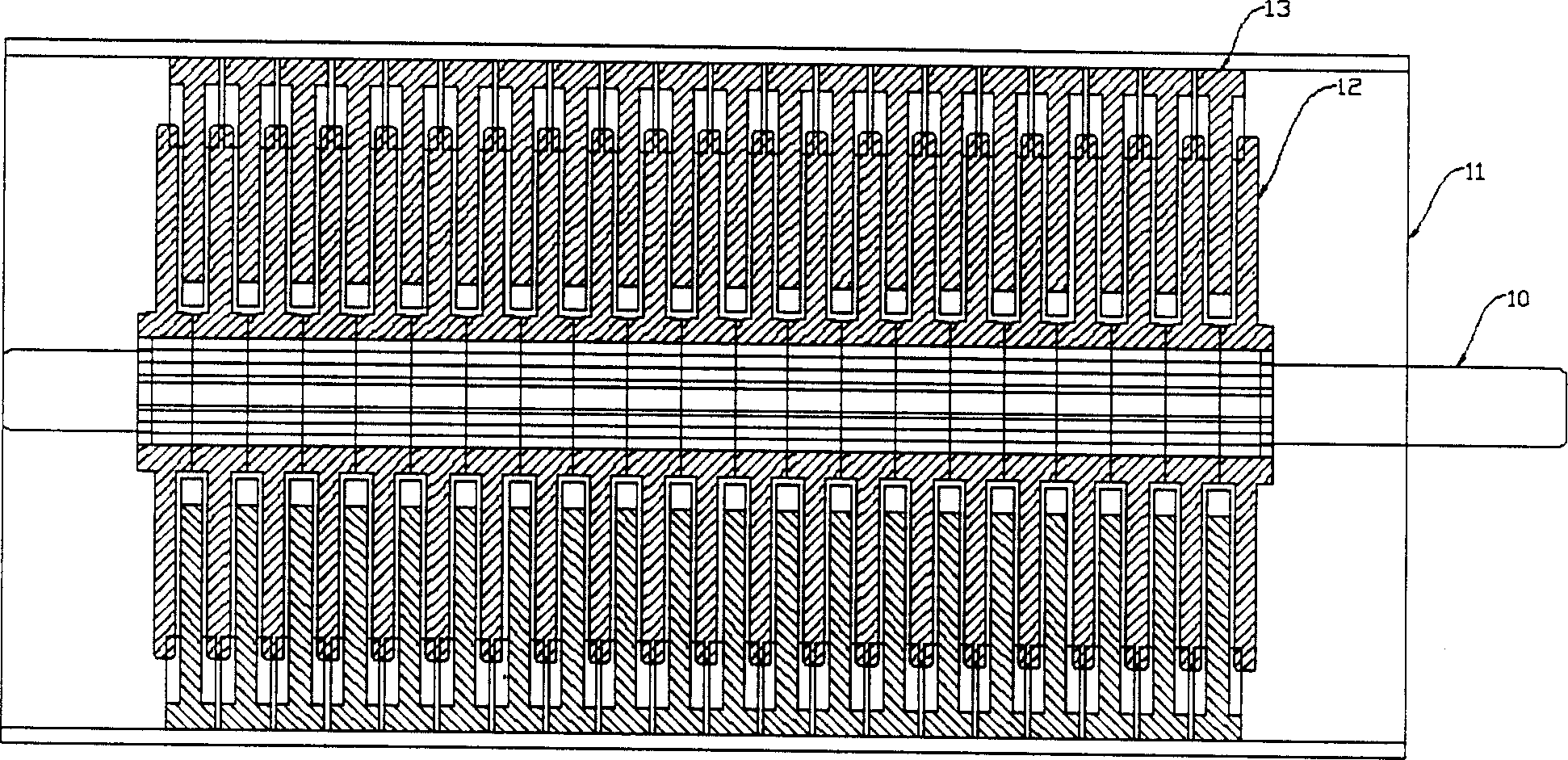
[0022] The ceramic generator consists of a stator mounted on a casing 11 and a rotor mounted on a crankshaft 10 . The stator and the rotor are respectively composed of multiple sets of fixed pole pieces 13 and moving pole pieces 12 (see figure 1 ), are staggered to form a large variable capacitance, the number of fixed pole plates 13 forming the stator and the number of moving pole plates 12 forming the rotor can be selected according to actual needs.

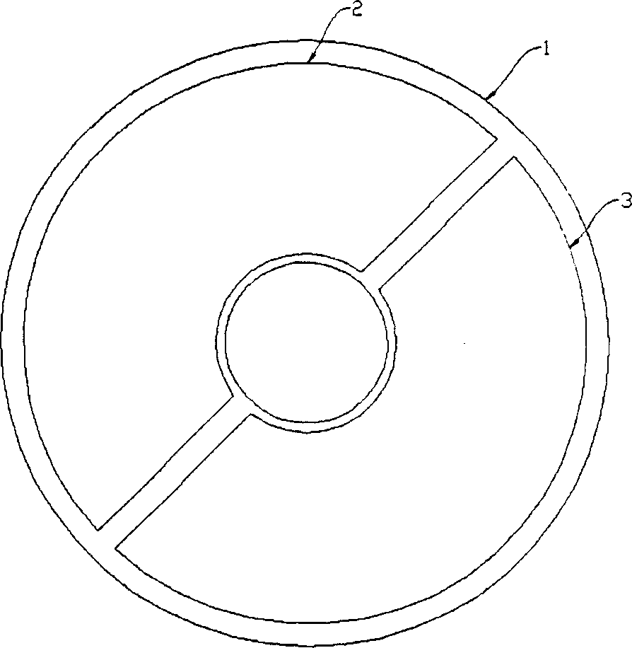
[0023] The structural representation of each pole plate 13 is shown in image 3 , is composed of fixed conductor sheets 2 and 3 fixed on the annular insulating substrate 1, and these two fixed conductor sheets constitute the first fixed electrode a and the second fixed electrode b respectively.

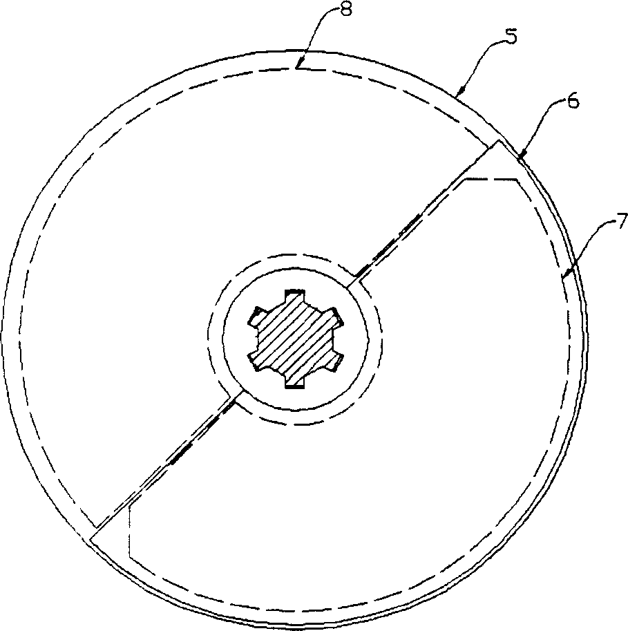
[0024] The structural representation of each moving pole piece 5 is shown in figure 2 , on the circula...


PUM


Abstract

The china generator is composed of the fixing pole and the moving pole, the moving pole is formed by the moving pole d and the reverse pole zone e mounted partly on one round isolating base board, the surface of the moving pole d is covered with the china medium layer, the fixing pole board, the fixing pole piece is formed by the first fixing pole a and the second fixing pole b mounting partly on the loop isolating base board, several fixing pole piece and moving pole pieces are mounted alternately, the stator and the rotor are formed separately. The moving pole d connects the charging circuit, the fixing pole a, b connect the exporting x, y line separately, the fixing pole piece can alter partly a, b, c fixing poles, the three phase is constructed. The invention realized the rotating changing capacitance generating electricity, the china medium is adopted, the bulk is reduced, it is easy to realize the single phase, three phase and the several phases, the efficiency of the generating electricity is high, it is changing capacitance generating electricity setting to realize the industrialization easily.

Description

technical field [0001] The invention relates to a generator, in particular to a variable capacitance ceramic generator. Background technique [0002] Existing power generation devices are mainly electromagnetic induction generators. Due to the need for coils and magnetically conductive materials, the structure is complex, the volume is large, the weight is heavy, and it is easy to generate heat during work. It must be properly cooled, and the general efficiency is limited to a certain extent. [0003] Many forms of variable capacitance generators have been proposed, but generally there are defects such as unreasonable structure of linear motion, small power generation, and difficulty in realization. Contents of the invention [0004] The invention provides a variable capacitance ceramic generator with simple structure and large capacity. [0005] The ceramic generator of the present invention includes a stator and a rotor. The stator is composed of a number of fixed pole ...

Claims


Application Information

Patent Timeline
Patent Type & Authority Applications(China)
IPC IPC(8): H02K1/12H02K11/00
CPCH02N1/08
Inventor 冯连阶
Owner 冯连阶
Why Eureka
Try Eureka