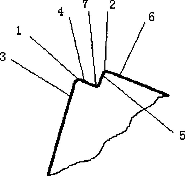
Double-head cutting tool in mechanical processing
A cutting tool and machining technology, which is applied in the field of metal cutting tools, can solve problems such as the inability to solve the interrelated problems of tool tips, cutting chatter, and increased wear of tool tips.
- Summary
- Abstract
- Description
- Claims
- Application Information
AI Technical Summary
Problems solved by technology
Method used
Image
Examples
Embodiment 1
[0031] Embodiment 1: The outer circle of the turning shaft is turned by a high-speed steel turning tool.
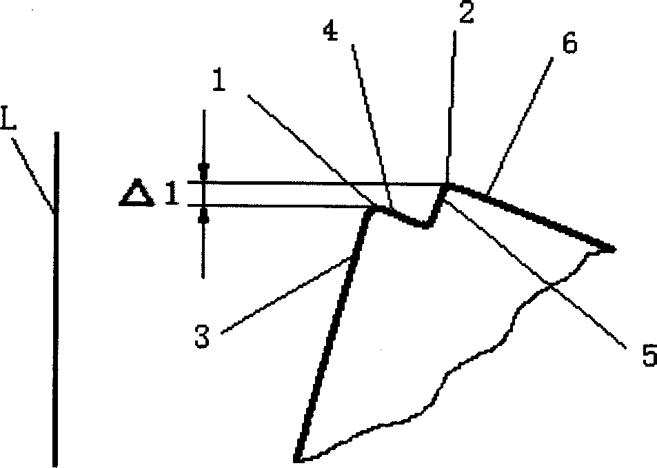
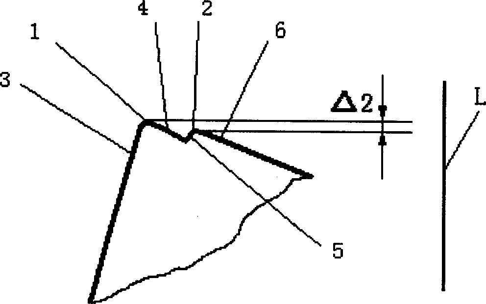
[0032] The workpiece material is 45, and the concave arc is processed by EDM at the original tool tip to form tool tip 1 and tool tip 2. The straight line distance between the two tool tips is 0.8mm, and the arc radius of the concave arc is 0.5. Tip 2 for fine grinding. In the direction parallel to the normal of the workpiece surface to be processed and pointing to the surface to be processed, the tool tip 2 has a protrusion of 0.15mm compared with the tool tip 1, and the back engagement is 1.2mm. The tool tip 1 participates in rough machining, and the tool tip 2 are responsible for finishing, and they are cut at the same time. During cutting, the tip 2 remains in good condition, resulting in a high-quality machined surface.
Embodiment 2
[0033] Embodiment 2: Carbide inserts are welded to the outer circle of the turning tool turning shaft.
[0034] The material of the workpiece is 40Cr, the material of the carbide blade is YT15, and the concave arc is machined by EDM at the original tip to form the tip 1 and the tip 2. The linear distance between the two tip is 1.0mm, and the concave arc is The radius of the arc is 0.6, and the tool tip 2 is ground. In the direction parallel to the normal of the workpiece surface to be processed and pointing to the surface to be processed, the tool tip 2 has a protrusion of 0.3mm compared with the tool tip 1, and the back engagement is 2mm. The tool tip 1 participates in rough machining, and the tool tip 2 In charge of finishing. The ground tip 2 remains in good condition during cutting, resulting in a high-quality machined surface.
Embodiment 3
[0035] Embodiment 3: Monitoring of the wear state of the cemented carbide blade welding turning tool.
[0036] The outer circle of the turning shaft, the workpiece material is 40Cr, and the carbide insert material is YT15. The concave arc is machined by EDM at the original tool tip to form tool tip 1 and tool tip 2. The straight-line distance between the two tool tips is 0.9mm , in the direction parallel to the normal of the workpiece surface to be processed and pointing to the surface to be processed, the tool tip 2 has an indentation of 0.1 mm compared with the tool tip 1, and the back engagement is 1.8 mm. During cutting, tool nose 1 works alone, and tool nose 2 does not participate in cutting. As the tool wears, the tool tip 1 moves backward until the tool tip 2 starts to participate in cutting, and two chips, one thick and one thin, appear, and the cutting force also changes significantly, reminding to stop and change the tool. After measurement, the wear value VN of the...
PUM
 Abstract
Description
Claims
Application Information
 - R&D
- Intellectual Property
- Life Sciences
- Materials
- Tech Scout
- Unparalleled Data Quality
- Higher Quality Content
- 60% Fewer Hallucinations
Browse by: Latest US Patents, China's latest patents, Technical Efficacy Thesaurus, Application Domain, Technology Topic, Popular Technical Reports.
© 2025 PatSnap. All rights reserved.Legal|Privacy policy|Modern Slavery Act Transparency Statement|Sitemap|About US| Contact US: help@patsnap.com


