
Air purification wall

An air and photocatalytic technology, applied in air conditioning systems, space heating and ventilation, chemical instruments and methods, etc., can solve the problems of few devices, difficult to achieve, helpless and so on

Inactive Publication Date: 2006-11-22
ARCELOR FRANCE (FR)
View PDF11 Cites 5 Cited by
  • Summary
  • Abstract
  • Description
  • Claims
  • Application Information

AI Technical Summary

Problems solved by technology

[0012] [08] However, devices according to the prior art provide little or no assistance in meeting the following requirements:
[0013] - The incorporation of an air cleaner into a building element requires, firstly, that the components have satisfactory structural mechanical properties, and secondly, a high compactness in terms of depth, which is due to the arrangement of the UV lamps in the correct orientation unattainable;

Method used


Image

  • Air purification wall
  • Air purification wall
  • Air purification wall

Examples


Embodiment Construction

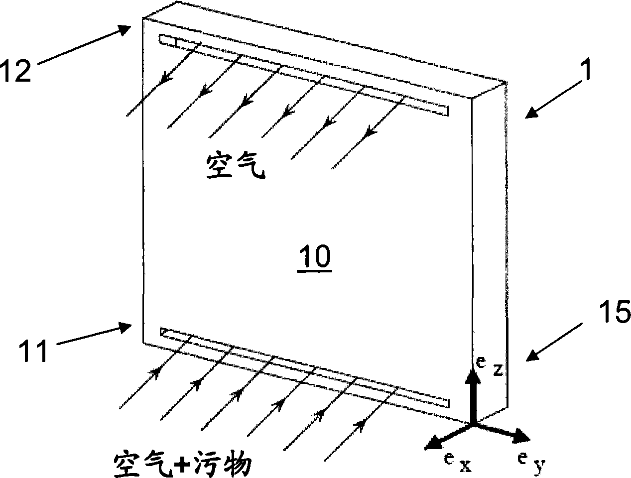
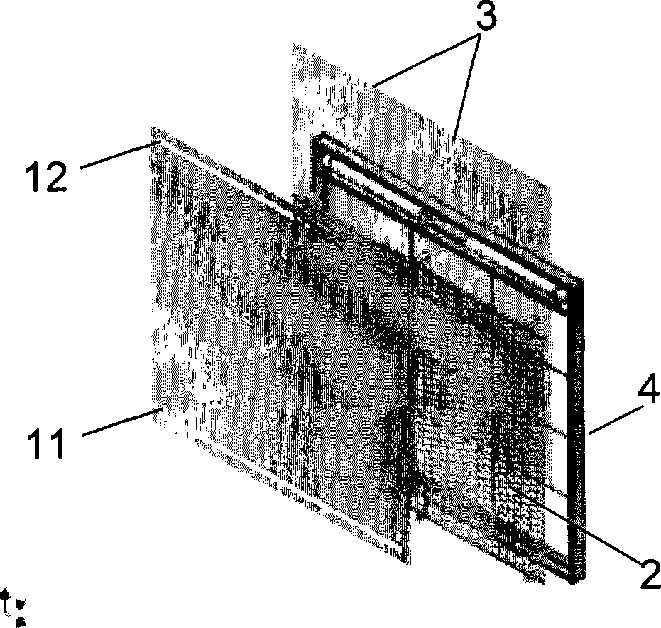
[0060] [36] figure 1 with figure 2 The working principle of the shown air-purifying wall 1 is heterogeneous photocatalysis in contact with titanium dioxide. The device includes an active wall 1, which adopts an open-loop working mode, and the active wall includes:

[0061] - an air inlet 11 located in the lower part of the front surface 10 of the active wall, through which the mixture of air and any possible pollutants enters the device;

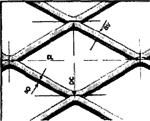
[0062] - one or several grids 2 located inside the active wall, they are made of porous metal, and titanium dioxide is deposited thereon, the grid is irradiated by the irradiation device with UVA lamp 3, to excite the titanium dioxide film layer;

[0063] - An opening 12 at the top of the front face 10 of the active wall, through which the air which has been cleaned of pollutants is discharged. The air flow is generated either by a fan (convection or forced circulation) or due to a temperature rise (natural circulation) which is due to t...


PUM

PropertyMeasurementUnit
widthaaaaaaaaaa
reflectanceaaaaaaaaaa

Abstract

The invention relates to an appliance for the continuous photocatalytic purification of the air in a room, said appliance preferably being in the form of a wall (1) and comprising an external steel structure, an opening (11) for the admission of the air to be processed, an internal metallic framework (4) to which a plurality of UVA lamps (3) are fixed, a photocatalytic filter (2), and an opening (12) for discharging the purified air. The inventive appliance is characterised in that the photocatalytic filter comprises at least one metal grating (2) covered by a film containing titanium dioxide (TiO2 ), mainly in an anatase phase, in order to maximise the surface of the photocatalyst illuminated by the UVA light.

Description

technical field [0001] [01] The present invention relates to an air purification device, which works on the principle of heterogeneous photocatalysis when in contact with titanium dioxide, preferably in the form of a wallboard. [0002] [02] The invention also relates to an air reduction method implemented by said device. Background technique [0003] [03] As a result of research on the phenomenon of photoinduced water splitting, heterogeneous photocatalysis has been recognized since the 1970s. This technique consists in performing irradiation on a semiconductor (usually titanium dioxide) with natural sunlight or artificial UV light sources (λ<400 nm). The semiconductor material will be excited, which will make the valence band electrons e - Excited into the conduction band of the semiconductor (reduction process). The corresponding hole h + (Oxidation) will react with the OH group adsorbed on the surface of the semiconductor so as to form a highly oxidative hydroxyl ...

Claims


Application Information

Patent Timeline
Patent Type & Authority Applications(China)
IPC IPC(8): B01D53/88A61L9/20B01D53/86E04C2/00
CPCA61L9/205B01D53/86B01D53/885B01D2255/802F24F8/167B01D53/88A61L9/20E04C2/00
Inventor L·热龙R·维南德L·德比
Owner ARCELOR FRANCE (FR)
Learn More