
High-pressure heat treatment furnace

A heat treatment furnace, high pressure technology, applied in furnaces, furnace cooling, cooking furnaces, etc., can solve the problems of increased maintenance costs, limited cooling capacity, low cooling capacity, etc., to improve the cooling effect, shorten the cycle time, and improve the cooling performance. Effect

Inactive Publication Date: 2006-11-22
IHI CORP +1
View PDF2 Cites 7 Cited by
  • Summary
  • Abstract
  • Description
  • Claims
  • Application Information

AI Technical Summary

Problems solved by technology

[0009] (1) After setting the water jackets 4 and 5 at figure 1 In the shown furnace container 1 and furnace cover 2, since the heat transfer area is limited to the inner wall area of ​​the pressure vessel 3, the cooling area is insufficient and the cooling capacity is low
In addition, since the wall thickness of the pressure vessel 3 has a thickness capable of withstanding high pressure, it is difficult to sufficiently cool the inner wall of the pressure vessel 3 even if the outer wall of the pressure vessel 3 is cooled with water.
The cooling capacity is limited by this
[0010] (2) When the water-cooled pipe 12 is set in such as figure 2 In the form of the inner wall of the furnace container 2 shown, the water-cooling tube 12 itself is expensive, so it is uneconomical in terms of cost burden, and it is necessary to increase the diameter of the furnace to ensure the installation space of the water-cooling tube 12
There is also the risk of water leakage and air leakage of the water-cooled pipe 12 in addition.
And when the water-cooling pipe 12 is clogged with scale and the like and the water flow is reduced, not only the cooling effect cannot be obtained, but also there is a risk of damaging the water-cooling pipe 12.
[0011] (3) After internal circulation fan 19, motor 20 and circulation gas guide plate 21 are arranged on such as Figure 4 In the form in the pressure vessel 3 shown, the structure is complicated by adding a fan and a motor, which causes an increase in manufacturing cost.
In addition, the user's power supply equipment and operating costs also increase with the supply of electric power to the motor.
There is also the risk of failure due to damage to the bearing, etc., and the maintenance cost will also increase
In addition, under the action of the wind pressure of the fan, it may not be possible to process light processed objects
Moreover, the motor capacity is limited by the installation space of the motor, thereby limiting the cooling capacity

Method used


Image

  • High-pressure heat treatment furnace
  • High-pressure heat treatment furnace
  • High-pressure heat treatment furnace

Examples


Embodiment Construction

[0034] Below, based on Figure 5 as well as Image 6 Preferred embodiments of the present invention will be described in detail.

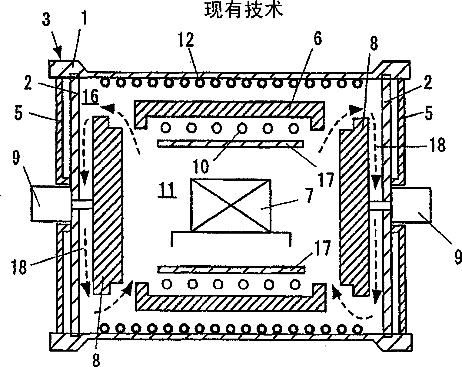
[0035] Figure 5 It is a schematic structural view showing an embodiment of the high-pressure heat treatment furnace of the present invention. exist Figure 5 In , reference numeral 3 is a pressure vessel including a hollow cylindrical furnace vessel 1 and a flat furnace cover 2 closing both ends of the furnace vessel 1 . This pressure vessel 3 is constructed so that the internal pressure can be controlled. In addition, a water jacket is provided on the outer periphery of the furnace container 1 , and cooling water is circulated inside as a refrigerant to cool the furnace container 1 .


PUM


Abstract

A high-pressure heat treatment furnace, comprising a pressure vessel having a furnace container and a furnace cover closing the furnace container and allowing an internal pressure to be controlled, heat-insulating walls installed in the pressure vessel, opened oppositely to the furnace cover, and forming a heating chamber for storing a treated material therein, a heat-insulating cover driven to open and close the opening part of the heat-insulating wall, a heater installed in the heating chamber to heat the treated material, and a plurality of cooling fins installed on the inner surface of the furnace cover to cool gases in the pressure vessel.

Description

technical field [0001] The present invention relates to a high-pressure heat treatment furnace for heat-treating metals such as superhard alloys, ceramics, and composite materials with a high pressure of 1 MPaG or higher, and more specifically relates to a high-pressure heat treatment furnace capable of rapid cooling in a furnace. Background technique [0002] In high-pressure heat treatment furnaces that heat treat cemented carbide, ceramics, etc. at high pressures above 1 MPaG, how to shorten the cooling time of the furnace in order to shorten the cycle time and improve the quality of the processed products has become an important issue. figure 1 For example, it is a schematic structural view of a conventional high-pressure heat treatment furnace disclosed in Patent Document 1 below. exist figure 1 Among them, reference numeral 3 is a pressure vessel composed of a furnace vessel 1 and a furnace cover 2 that closes both ends of the furnace vessel 1. Water jackets 4 and 5 a...

Claims


Application Information

Patent Timeline
IPC IPC(8): F27B17/00F27D9/00F27B5/04F27B5/14F27B5/16F27D7/06
CPCF27B5/04F27B5/14F27B2005/167F27D7/06F27D9/00
Inventor 铃木晶石川博敏浜田达也木屋升永井规辉
Owner IHI CORP
Features
  • Generate Ideas
  • Intellectual Property
  • Life Sciences
  • Materials
  • Tech Scout
  • Unparalleled Data Quality
  • Higher Quality Content
  • 60% Fewer Hallucinations
Learn More