
Dispensing device

A technology of release position and indexing mechanism, which is applied in the direction of dispensing device, packaging, transportation and packaging, etc., can solve the problems of powder adhesion and removal, and achieve the effect of reducing obstruction

Active Publication Date: 2006-11-29
PFIZER INC
View PDF1 Cites 26 Cited by
  • Summary
  • Abstract
  • Description
  • Claims
  • Application Information

AI Technical Summary

Problems solved by technology

Since the same tray and upstanding walls are used for all cells, one problem is that powder can adhere to the trays and upstanding walls and then be dislodged

Method used


Image

  • Dispensing device
  • Dispensing device
  • Dispensing device

Examples


Embodiment Construction

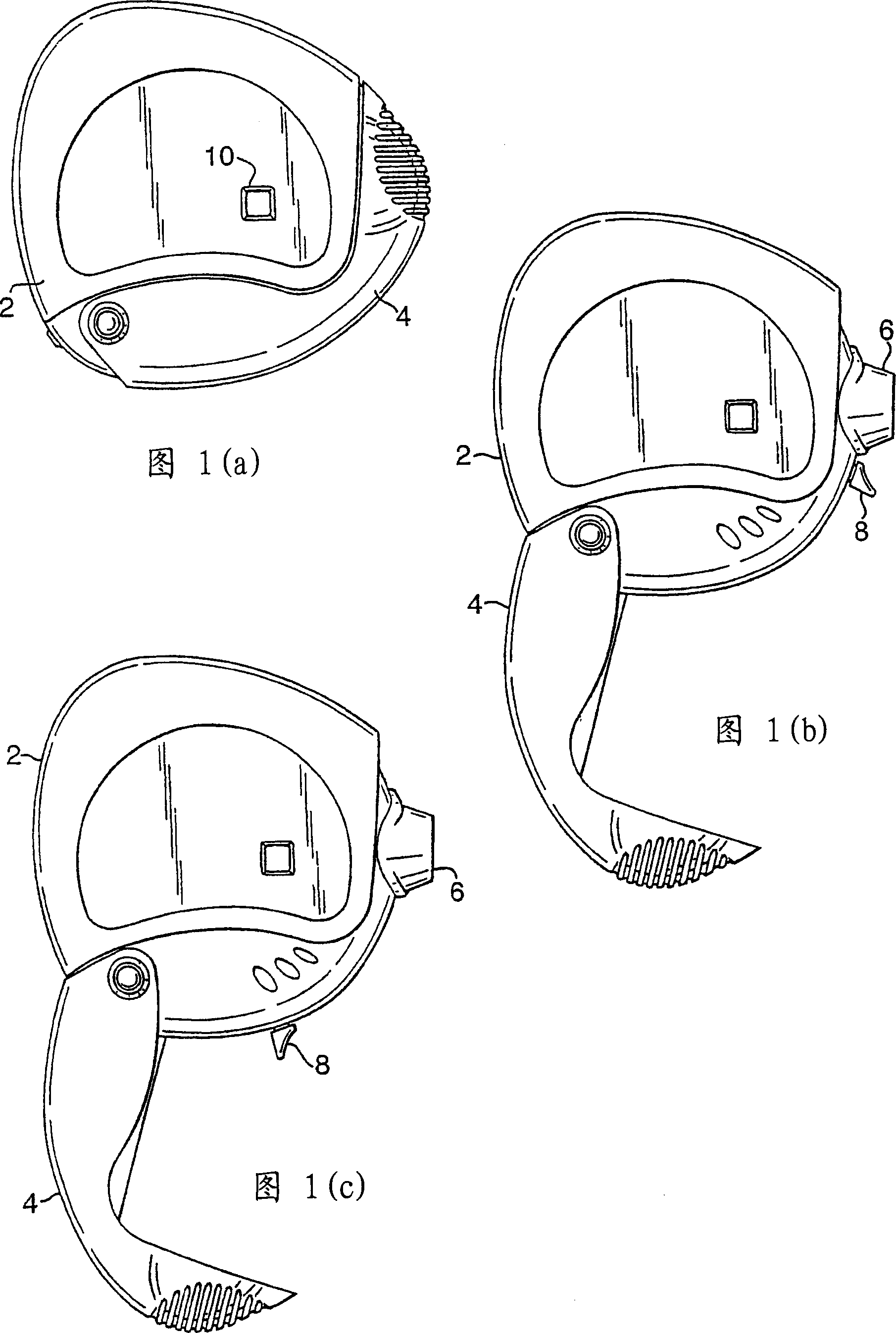
[0146] A preferred embodiment of the invention is an inhalation device from which a user can inhale successive doses of medicament in dry powder form. This preferred embodiment is shown in Figures 1(a) to (c).

[0147] The device comprises a housing 2 on which a mouth cover 4 is rotatably supported.

[0148] To use the device, the mouth cap 4 is pivoted away from the housing 2 . As shown in FIG. 1(b), the mouth portion 6 is thus exposed. The mouth 6 may be integrally formed with the housing 2, but it may also be formed as a separate component mounted with the housing 2 as described below. This allows the material properties of the mouth 6 and housing 2, eg colour, to be easily changed according to the needs of the device.

[0149] As shown in FIG. 1( b ), the arming lever 8 protrudes from the housing 2 at a position adjacent to the mouth 6 . The arming lever 8 is mounted for rotation within the device about a central axis (further described below). In this way, the user c...


PUM


Abstract

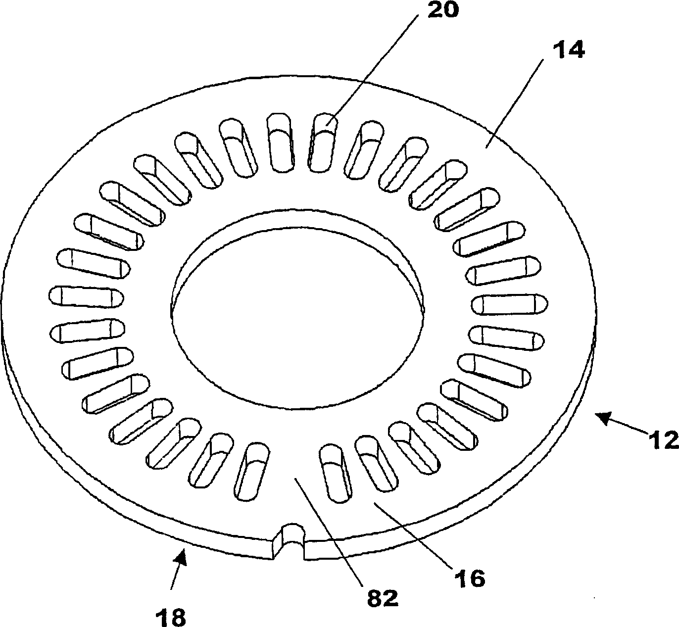
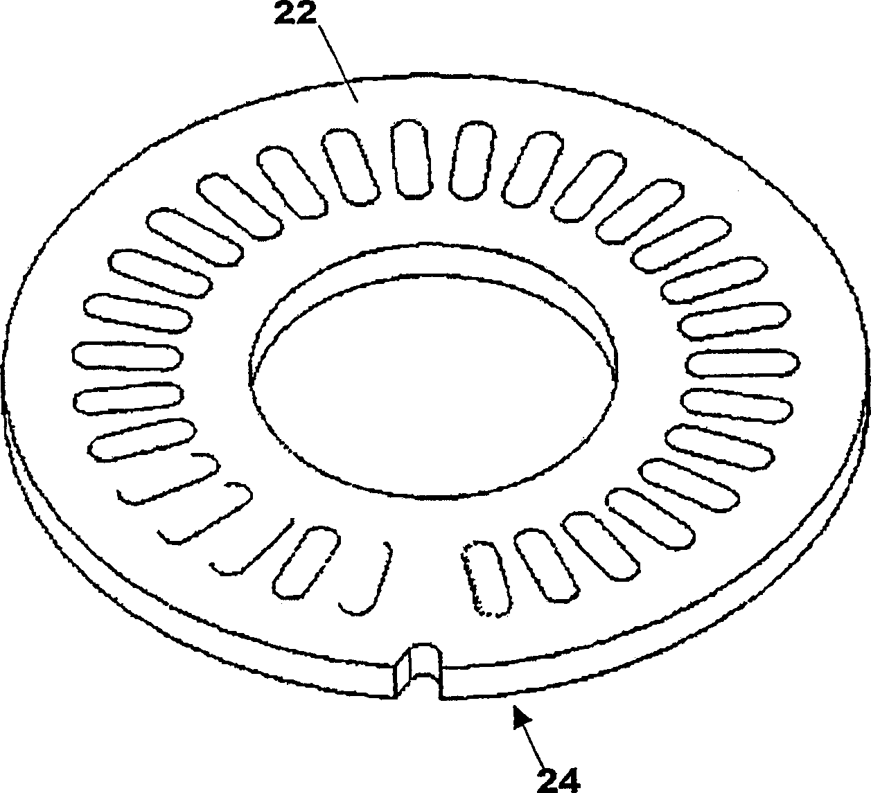
A device for dispensing individual doses of powder from respective pockets of a disc-shaped carrier by outwardly rupturing a lidding foil by means of pressure on an opposite side surface, the device providing individual respective deaggregation flow paths for each pocket, split airstreams allowing improved entrainment of powder, a cam mechanism for outwardly rupturing the pockets, an indexing mechanism linked to the cam mechanism and a dose counter.

Description

technical field [0001] The present invention relates to a dispensing device, more particularly for dispensing individual doses of powder from individual pockets of a tray. Background technique [0002] Various devices are known for dispensing medicaments in powder form for inhalation. Known devices include a reservoir of powdered medicament from which the required doses are metered. Known devices also include a tray with a plurality of pouches containing individual doses of powder. These brackets are usually cell parts. All of these devices face the problem of providing reliable, repeatable and precise inhalation of powder. [0003] There are problems in ensuring that all doses of powder to be dispensed are confined to the inspiratory airflow. Additionally, some powders intended for inhalation may adhere to surfaces within the device. This reduces the inhaled dose. More importantly, however, after multiple uses, the previously attached powder may be dislodged, thereby ...

Claims


Application Information

Patent Timeline
Patent Type & Authority Applications(China)
IPC IPC(8): A61M15/00
CPCA61M2015/0048A61M2015/0031A61M2015/0061A61M15/0061A61M15/0048A61M15/0026A61M2202/064A61M15/0031A61M2015/0026G06M1/248B65D83/0445A61M15/0068A61M15/0045A61M15/0073A61M2015/0068A61M15/0075A61M15/00A61M13/00A61J3/02A61M15/0021A61M15/0058B65D83/06
Inventor 彼得·J·豪齐戈约翰·K·康韦马丁·D·珀尔安德鲁·M·布赖恩特
Owner PFIZER INC
Learn More