Full automatic technique of graded deferrization, and equipment

A fully automatic and advanced technology, applied in the field of magnetic separation, can solve the problems of not realizing the effect of iron removal and high efficiency of iron removal, and achieve the effect of avoiding the weakening of adsorption capacity, improving work efficiency, and avoiding the easy damage of magnetic rods

Inactive Publication Date: 2006-12-06
山东润科机电设备有限公司
View PDF0 Cites 19 Cited by
  • Summary
  • Abstract
  • Description
  • Claims
  • Application Information

AI Technical Summary

Problems solved by technology

The applicant has successively developed curtain type slurry iron remover, compound iron remover, and electromagnetic iron remover

Method used


Image

  • Full automatic technique of graded deferrization, and equipment
  • Full automatic technique of graded deferrization, and equipment
  • Full automatic technique of graded deferrization, and equipment

Examples


Embodiment 1

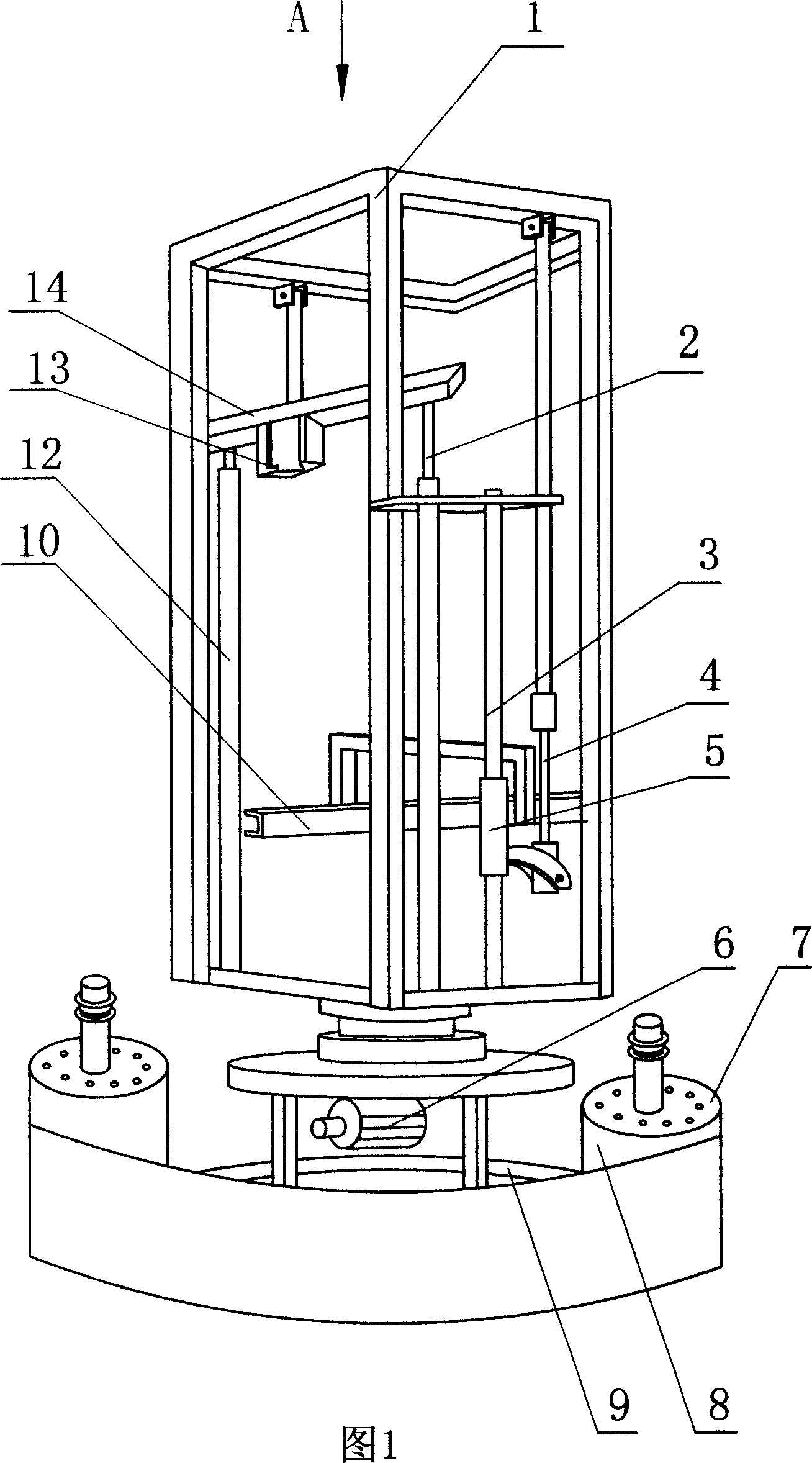
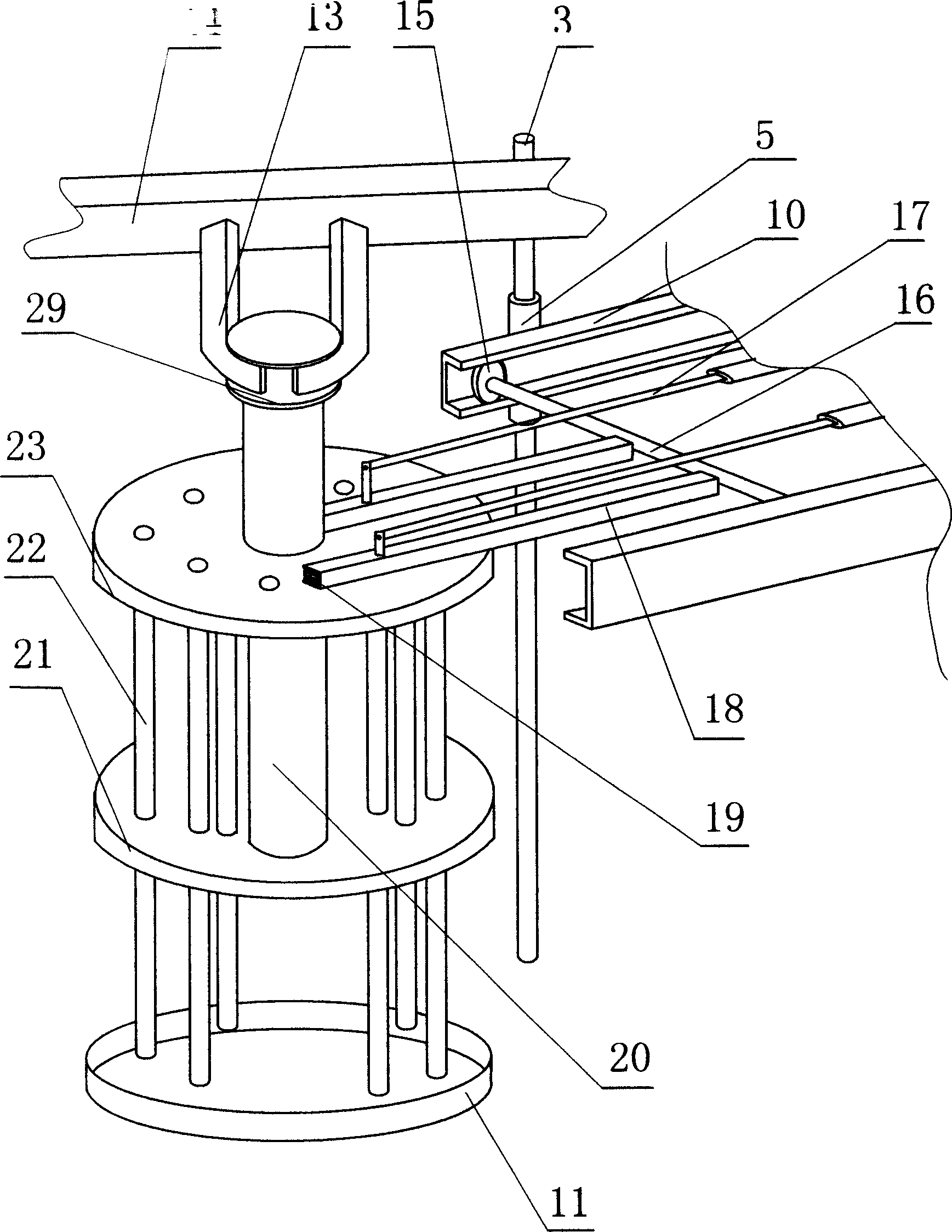
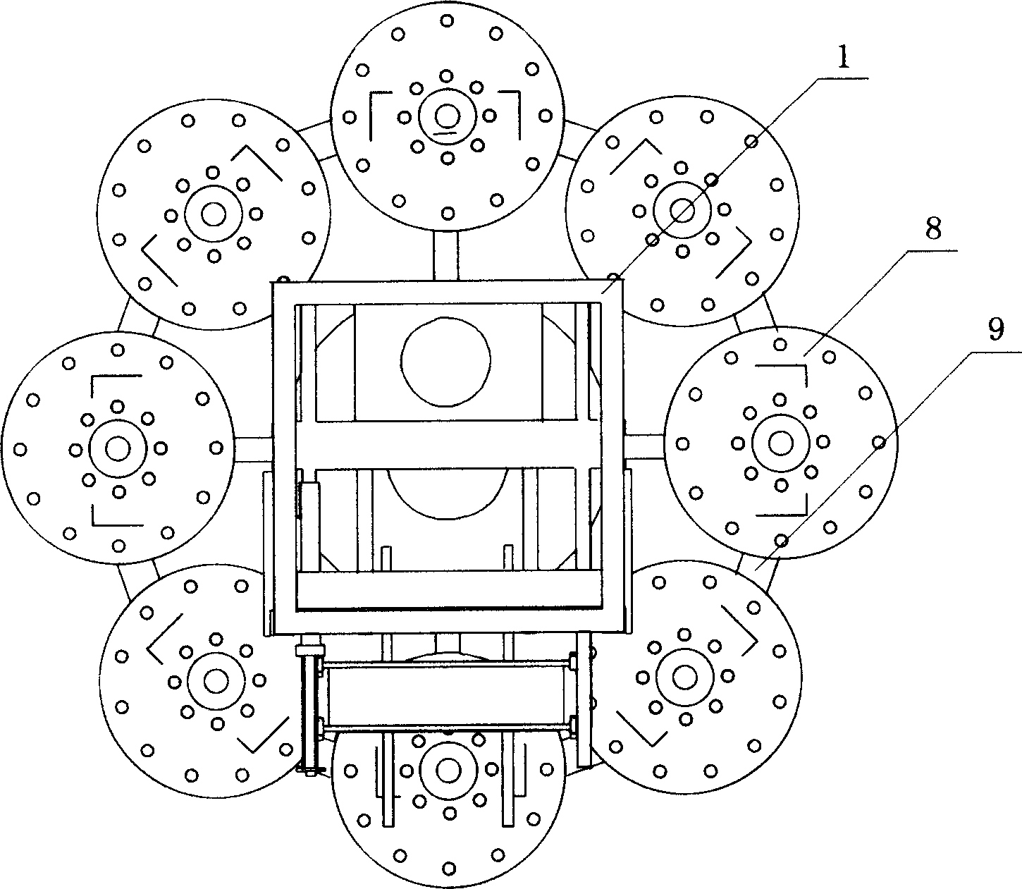
[0032] Figure 1, image 3 As shown, a plurality of slurry tanks 8 are placed on the bottom frame 9 in a ring shape, and each slurry tank is connected. As can be seen from Fig. 1, the reducer 6 is fixedly connected to the bottom frame 9, and the power output shaft of the reducer 6 is connected with the frame 1, and the frame 1 can slowly rotate when the reducer is working. A guide column 3 is erected on the frame 1, and a sliding sleeve 5 is set on the guide column 3, and the sliding sleeve 5 can slide up and down along the guide column 3. The sliding sleeve 5 is connected with the hydraulic column 4 of the vertical oil cylinder, and when the hydraulic column of the vertical oil cylinder moves up and down, the sliding sleeve 5 is driven to move up and down; the sliding sleeve 5 is fixed with a guide rail 10 . figure 2 Among them, there is a coupling shaft 16 between the two guide rails 10, and rollers 15 are installed at the two ends of the coupling shaft 16, and the rollers 1...

Embodiment 2

[0037] Such as Image 6 As shown, the feature of this embodiment is that the slurry tank 31 is arranged in a linear determinant, and guide rails 29 are respectively arranged on both sides of the slurry tank, and sliding frames 40 are installed on the guide rails 29 . The carriage 40 moves along the guide rail 29 under the action of the driving mechanism. A guide column 36 is set in the slide frame 40, and a sliding sleeve 38 is set on the guide column 36, and the sliding sleeve is connected with a boom 41, and the sliding sleeve 38 is connected with the hydraulic column of the vertical oil cylinder. Fix the slot 37 on the top plate 35 of the magnetic suction roller 30, the boom 41 can just stretch into the slot 37, the fastener is fixed on the scraper 32 of the magnetic suction roller 30, the hydraulic column 33 of the horizontal oil cylinder is connected to the pulling bracket 34, and the pulling bracket 34 ends can be fastened on the scraper fastener.

[0038] The working ...


PUM


Abstract

A full-automatic classifying and iron-removing apparatus is composed of several slurry pools communicated with each other, multiple magnetically sucking rollers consisting of magnetic rods in each pool and with scraper, a machine frame with hanging mechanism for driving said rollers to come in pool and scraper controlling unit, and a driver for driving the machine frame to the position above pool. Its technology is also disclosed.

Description

technical field [0001] The invention belongs to the field of magnetic separation for separating solid materials from fluids, and in particular relates to a process for removing iron filings from slurry by using a permanent magnet and a device for realizing the process. Background technique [0002] In the fields of chemical industry and ceramics, liquid slurry is often used as raw material to produce solid finished products. Since the minerals from the earth's crust contain a certain amount of iron, the resulting slurry contains a large amount of iron filings. In the field of building ceramics for the manufacture of floor tiles or interior and exterior wall tiles, iron filings in the slurry will cause black spots in the produced floor tiles, which affects product quality. In view of this, slurry iron removal has become an important link in the production of ceramic enterprises. With the improvement of people's living standards, people have higher and higher requirements fo...

Claims


Application Information

Patent Timeline
IPC IPC(8): B03C1/02
CPCB03C1/284B03C1/286B03C2201/18
Inventor 赵维珂赵凌霄
Owner 山东润科机电设备有限公司
Why Eureka
Try Eureka