Microinjection forming mould for metal and ceramic minitype parts forming

A technology for miniature parts and forming molds, applied in the field of powder metallurgy, can solve the problems that traditional injection machines cannot be used together, and achieve the effect of reducing production costs, reducing investment and ensuring accuracy

Inactive Publication Date: 2006-12-13
UNIV OF SCI & TECH BEIJING
View PDF0 Cites 9 Cited by
  • Summary
  • Abstract
  • Description
  • Claims
  • Application Information

AI Technical Summary

Problems solved by technology

But at present, there is no matching mold for micro-injection molding of metals and ceramics. The main reasons are as follows: 1. The research on micro-injection molding technology in the world is all performed on micro-injection machines. Traditional injection machines cannot be used together

Method used


Image

  • Microinjection forming mould for metal and ceramic minitype parts forming
  • Microinjection forming mould for metal and ceramic minitype parts forming

Examples


Embodiment Construction

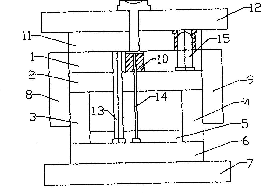
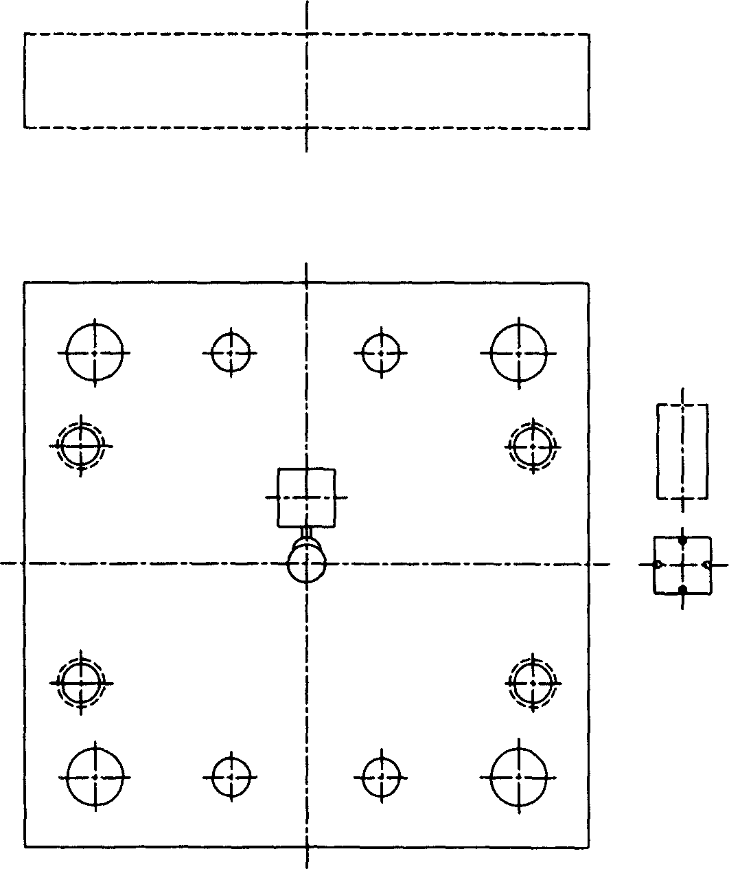
[0019] figure 1 , figure 2 As one embodiment of the present invention, the mold for microinjection molding includes a movable mold and a static mold. The cold trough on the movable mold plate 1 is 8×6mm, the cross section of the injection runner is rectangular, and the runner is 2×1.5×2mm. The cross section of the mosaic block in the movable mold plate 1 is a square of 12×12 mm, and the surface is 2 mm lower than the parting surface of the movable mold plate 1 , thereby forming a groove of 12×12×2 mm. Corresponding to the groove of 12×12×2 mm, the size of the single crystal silicon wafer is 8×8×0.6 mm, and the diameter of the thimble 14 is 1.5.

[0020] Among them, the size of the 8×8mm monocrystalline silicon wafer can be adjusted according to the needs, and the size of the cross-section of the 12×12×2mm groove and the cross-section of the four ejector pins with a cross-sectional area of ​​1.5 should also be adjusted accordingly.

[0021] In order to ensure good unifor...


PUM

PropertyMeasurementUnit
diameteraaaaaaaaaa

Abstract

The invention relates to a micro-injection shaping mold for metallic and ceramic microelements, belonging to powder metallurgical technology. Said mold comprises moving mold and static mold; said moving mold concludes: mold board, supporting board, heating plate; static mold includes two static mold plates; micro-injection shaping mold comprises heating and cooling device, heating device is fixed on moving mold, two heating plates are installed on mold board, heating coil is embedded inside heating plate; said cooling device is circulated water cooling type, moving and static mold are equipped with a unit of cooling device respectively; the mono-crystalline silicon slice employs deep etching technology and forms die cavity for micro element; mono-crystalline silicon slice is set on moving mold. The invention is characterized in that: the injection shaping for micro metallic and ceramic element with size smaller than 1mm is realized on traditional injecting machine, accuracy of micro element is guaranteed, investment and production cost are reduced.

Description

technical field [0001] The invention belongs to the technical field of powder metallurgy, in particular to a mold for micro-injection molding used for forming metal and ceramic micro-parts. Background technique [0002] The rapid development of microsystem technology in recent years has greatly improved the performance and performance of three-dimensional micro-complex components used in micro-engineering, such as micro-molds, micro-mechanical structures for sensors and accelerators, biosensors, micro-fluidic elements, and micro-reactors. There are increasingly urgent requirements for large-scale production. However, the development of microsystem technology is restricted by processing, and traditional processing methods are far from being competent. Although existing micro-processing technologies, such as micro-cutting, laser cutting, silicon etching technology and LIGA technology, have many advantages However, it is often limited by the lack of processing materials, and i...

Claims


Application Information

Patent Timeline
Patent Type & Authority Applications(China)
IPC IPC(8): B22F3/22B28B1/24
Inventor 尹海清曲选辉贾成厂杜美娜
Owner UNIV OF SCI & TECH BEIJING
Why Eureka
Try Eureka