
Horizontally wire-feeding split type micro electric spark wire cutting device

A technology of EDM wire and cutting device, applied in electrode manufacturing, electric processing equipment, metal processing equipment, etc., to achieve the effect of convenient installation and adjustment, improved processing accuracy and small size

Inactive Publication Date: 2006-12-13
SHANGHAI JIAO TONG UNIV
View PDF1 Cites 12 Cited by
  • Summary
  • Abstract
  • Description
  • Claims
  • Application Information

AI Technical Summary

Problems solved by technology

[0005] The purpose of the present invention is to solve the problems of the existing wire electric discharge machine tool (or device), and a split type micro wire electric discharge device with horizontal wire feeding is designed

Method used


Image

  • Horizontally wire-feeding split type micro electric spark wire cutting device

Examples


Embodiment Construction

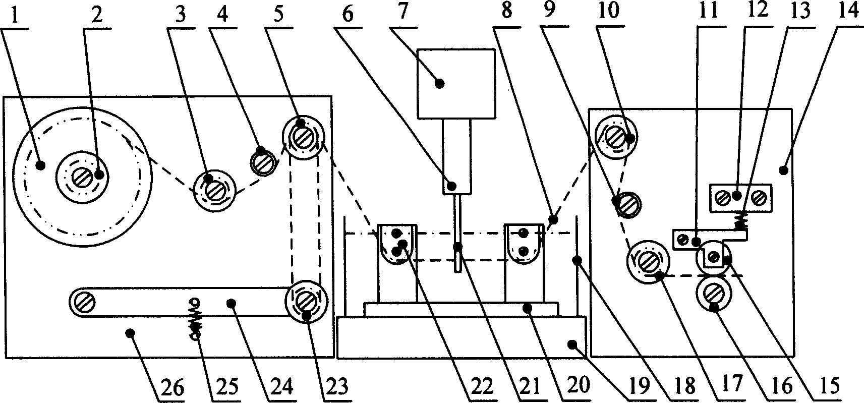
[0015] As shown in the figure, the present invention is composed of three parts: a tension control device, a wire running device and a wire receiving device.

[0016] 1. Tension control device

[0017] The tension control device consists of a wire storage drum 1, a compression spring 2, the first single-filament track fixed guide wheel 3, the first felt ring 4, double-filament track fixed guide wheels 5, single-filament track floating guide wheels 23, a lever 24, and a tension spring 25 and tension control device carrier 26 composition. The wire storage drum 1, the compression spring 2, the first monofilament fixed track guide wheel 3, the first felt ring 4, the double thread track fixed guide wheel 5, and the fixed end of the lever 24 (the left end in the figure) are all fixed by screws at tension. On the control device carrier 26, except the first felt ring 4, all can rotate around the screw; the single wire track floating guide wheel 23 is fixed on the movable end (the rig...


PUM


Abstract

The invention discloses a split fine electric spark wire-electrode cutting device, belonging to field of special type process. The invention employs split structure, and comprises tension control device, wire proceeding device and wire returning device. Said tension control device is installed on left or right of working liquid tank, wire proceeding device is set inside working liquid tank, wire returning device is located on left or right side of working liquid tank, work piece is installed on main axle, and the axis Z and Y drive horizontal electrode wire to cut. The invention employs horizontal wire location, which simplifies machine structure, realizes miniaturization; and the immersion and working liquid spraying can be realized. The invention employs V wire nozzle to realize electrode wire accurate location, reduce shake and increase processing accuracy and coarse degree of processing surface.

Description

technical field [0001] The invention relates to a device in the technical field of special processing, in particular to a split-type fine wire electric discharge cutting device with horizontal wire movement. Background technique [0002] Wire-cut electric discharge machining is a processing method that uses the thermal effect generated by spark discharge to etch away the workpiece material. It has the advantages of not being limited by the mechanical properties of the workpiece material such as strength and hardness, and has no macro cutting force. It is especially suitable for difficult-to-machine materials and The processing of complex shape parts is widely used in aviation, aerospace, automobile, electronics, mold, light industry and other industries. In recent years, with the development, maturity and application of micro-machines, the demand for micro-parts (such as micro-gears, micro-splines, micro-connectors, micro-moulds, micro-shaped hollows and other typical parts)...

Claims


Application Information

Patent Timeline
Patent Type & Authority Applications(China)
IPC IPC(8): B23H7/02B23H7/26B23H7/10
Inventor 赵万生
Owner SHANGHAI JIAO TONG UNIV
Learn More