
Vertical reduction tank and reduction furnace device for metal smelting

A reduction tank and reduction furnace technology, applied in the direction of improving process efficiency, can solve the problems of short life of reduction tank, waste of raw materials, failure to provide safety, etc., to eliminate waste of energy and raw materials, and avoid empty burning" and "" The effect of under-burning and improving the utilization rate of raw materials

Inactive Publication Date: 2006-12-13
刘伟杰
View PDF2 Cites 13 Cited by
  • Summary
  • Abstract
  • Description
  • Claims
  • Application Information

AI Technical Summary

Problems solved by technology

[0005] 2. The life of the reduction tank is short
At present, the average service life of magnesium reduction tank is only 2-3 months
[0006] 3. It is difficult to load and unload materials
Its narrow operating space makes loading and unloading difficult, low production efficiency and high labor intensity
[0007] 4. Unable to monitor the restore process
This often results in the phenomenon of "empty burning", that is, the reduction tank continues to be heated after the reduction reaction has been completed, thus causing a waste of energy; waste of raw materials
[0008] 5. Serious heat leakage
However, this approach has not yet been adopted
One reason is that the method provided by Pidgeon cannot effectively prevent the leakage of heat along the discharge channel, thereby reducing the heat utilization rate of the reduction furnace
Another reason is that Pidgeon failed to provide a proper discharge port cover opening device to avoid the threat to the operator's safety from the high temperature residue discharged quickly under the action of gravity

Method used


Image

  • Vertical reduction tank and reduction furnace device for metal smelting
  • Vertical reduction tank and reduction furnace device for metal smelting
  • Vertical reduction tank and reduction furnace device for metal smelting

Examples


Embodiment Construction

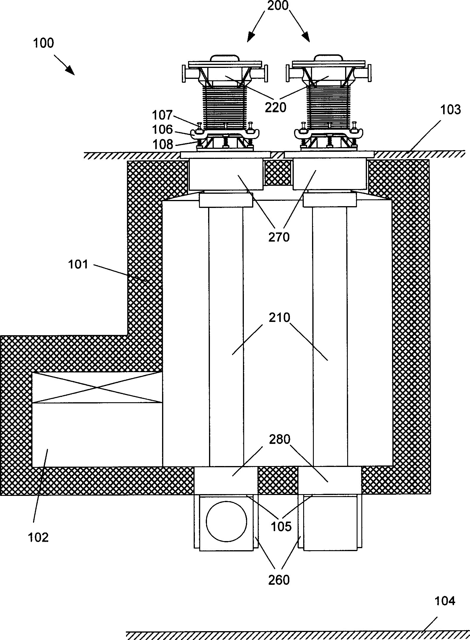
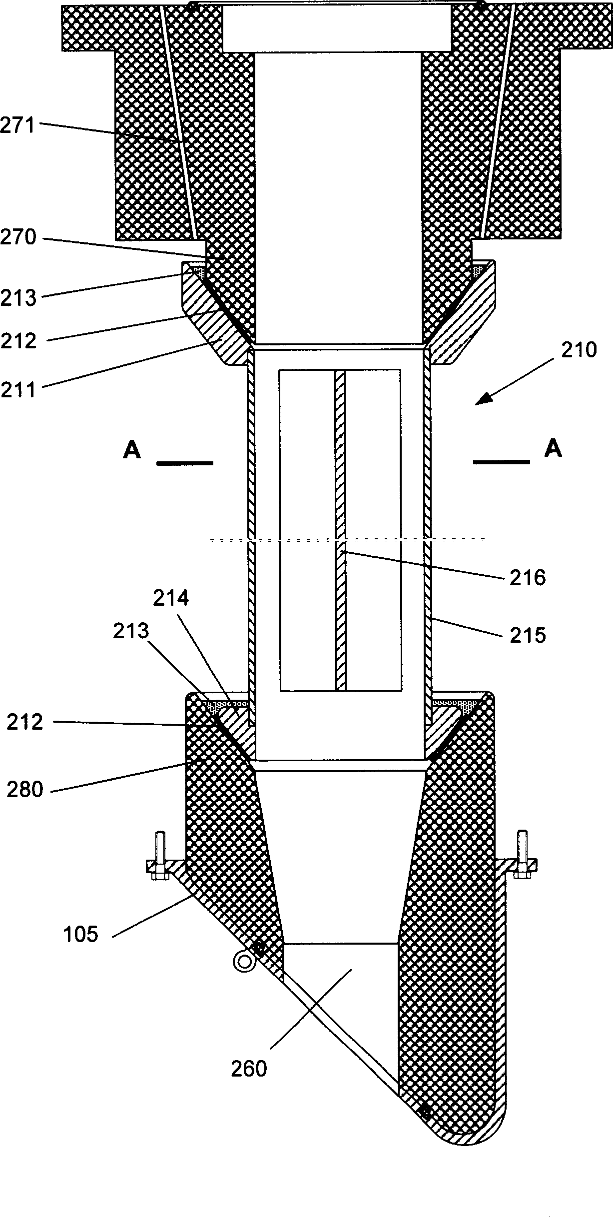
[0043] figure 1 Shown is a schematic cross-sectional view of a vertical reduction furnace (100) constructed using the vertical reduction tank of the present invention (one embodiment). The vertical reduction furnace (100) consists of a furnace body (101), a combustion chamber (102), a plurality of vertical reduction tanks (200) installed therein, an upper working platform (103) and a lower working platform (104). Heating of the reduction furnace (100) can be accomplished using any suitable heat source. Appropriate lifting and conveying devices (not shown) are installed on the upper working platform (103) for taking out reduced metal lumps and loading raw material balls. Appropriate conveying devices (not shown) are installed on the lower working platform (104) for unloading and conveying the reaction residues. The number and arrangement of the vertical reduction tanks (200) installed in the reduction furnace (100) can be flexibly changed according to factors such as design o...


PUM

PropertyMeasurementUnit
thicknessaaaaaaaaaa

Abstract

A leakage method of obstruction reducing furnace intrinsic heat towards the furnace outside along reduction bank; a method which can simultaneously strengthen the coefficient of overall heat transmission and creep resistance of the reduction bank; an air cooling method for metal ingot cylinder of the reduction bank; a method of carrying automatic shipping and delivery of the reduction bank using earth gravity; an on-line continuous monitoring method for matallic reducing process. A vertical reduction bank is built with the said method. A vertical reducing furnace built with the said vertical reduction bank is characterized in that it is of high calorific efficiency, short reduction cycle, long reduction bank age and automatic charge, and can perform on-line observation for reduction process.

Description

technical field [0001] The present invention relates to a reduction equipment suitable for the Pidgeon metal extraction method, more precisely, relates to the use and manufacture of a vertical reduction tank and a reduction furnace device. [0002] Although the description of the present invention takes the refining of metal magnesium as an example, it is also applicable to the refining of other volatile metals, such as calcium, strontium, zinc and the like. Background technique [0003] Invented in the 1940s, the Pidgeon metal extraction method (US Patent No. 2330143, Canadian Patent No. 415764, 415765 and 463416) is a method suitable for refining various volatile metals (such as magnesium, calcium, strontium, zinc, etc.) pyrometallurgical technology. The process includes the following steps: 1) put the raw material balls made by mixing and pressing the mineral material and reducing agent powder into a horizontally placed vacuum reduction tank and heat them; 2) under high ...

Claims


Application Information

Patent Timeline
Patent Type & Authority Applications(China)
IPC IPC(8): C22B5/16C22B9/02C22B26/22C22B19/04C22B61/00
CPCY02P10/20
Inventor 刘伟杰
Owner 刘伟杰
Learn More