Gas heating stove

A technology of gas heating and central processing unit, which is applied in the direction of lighting and heating equipment, fluid heaters, water heaters, etc., to achieve the effect of effective recycling

Inactive Publication Date: 2006-12-13
HAIER GRP CORP +1
View PDF1 Cites 11 Cited by
  • Summary
  • Abstract
  • Description
  • Claims
  • Application Information

AI Technical Summary

Problems solved by technology

[0005] The technical problem to be solved by the present invention is to provide a gas-fired heating stove, which solves the problems of sufficient condensation of water vapor in the flue gas discharged from the gas-fired heating stove and the effective recovery and utilization of heat

Method used


Image

  • Gas heating stove
  • Gas heating stove
  • Gas heating stove

Examples


Embodiment Construction

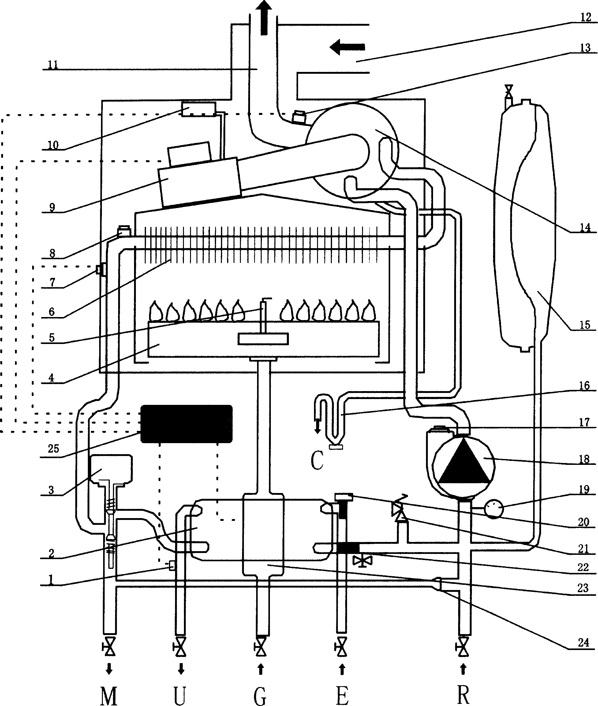
[0020] The invention provides a gas heating furnace, which realizes that the water vapor in the flue gas discharged from the gas heating furnace is fully condensed, and the heat is effectively recovered and utilized.

[0021] see figure 1 , which is a structural diagram of the gas heating furnace of the present invention.

[0022] 1 is the hot water temperature sensor; 2 is the plate heat exchanger; 3 is the three-way valve motor; 4 is the burner; 5 is the ignition / detection electrode; 6 is the main heat exchanger; 7 is the heating temperature sensor; 8 is the limit temperature Switch; 9 is variable speed fan; 10 is air pressure difference switch; 11 is flue gas discharge pipe; 12 is air inlet pipe; 13 is temperature sensor; 14 is condensing heat exchanger; 15 is closed expansion water tank; 16 is condensing Water drainage pipe; 17 is an automatic exhaust valve; 18 is a circulating water pump; 19 is a water pressure gauge; 20 is a water flow sensor; 21 is a safety valve; 22 i...


PUM


Abstract

The invention relates to a fuel gas heating furnace which comprises a main heat exchanger and a secondary heat exchanger, a water tank, a water tube, a temperature sensor, a central processing unit, a speed-variable fan whose rotation speed is controlled by the central processing unit, and a fuel gas rate valve whose output power is controlled by the central processing unit. The invention can fully condense the vapor and effectively recycle the heat of vapor in the discharged smoke.

Description

technical field [0001] The invention relates to a gas heating furnace. Background technique [0002] At present, most heating and hot water dual-purpose heating stoves use gas to work. During the use of ordinary gas dual-purpose heating stoves, about 10% of the heat is discharged with the flue gas, which causes a waste of energy. Because gas produces a large amount of water vapor when it is burned, 1 cubic meter of natural gas can produce 1.6 kilograms of water when it is completely burned. Therefore, the existing dual-purpose heating furnace mostly adopts a secondary heat exchange structure to condense the water vapor in the flue gas after the combustion of the gas. In this way, the heat in the flue gas after combustion of the gas can be reused to a certain extent. [0003] The application number is 03272510.8, and the Chinese utility model patent application titled "new gas heating / hot water dual-purpose boiler" discloses a dual-purpose gas heating boiler with secondary...

Claims


Application Information

Patent Timeline
Patent Type & Authority Applications(China)
IPC IPC(8): F24H1/14F24H9/20
Inventor 孙京岩闫小勤王任华曹立国李慎波
Owner HAIER GRP CORP
Why Eureka
Try Eureka