Heat conductive caulking pad with composite structure

A composite structure and gasket technology, used in semiconductor devices, cooling/ventilation/heating transformation, semiconductor/solid-state device components, etc. question

Inactive Publication Date: 2006-12-13
陈鸿文
View PDF0 Cites 7 Cited by
  • Summary
  • Abstract
  • Description
  • Claims
  • Application Information

AI Technical Summary

Problems solved by technology

However, in practical applications, the above three modes all have the following defects: the thickness of the caulking layer is not uniform after lamination, the film layer is uneven, and defects such as unshaped pores, air blocks or non-contact surfaces remain after lamination
Moreover, these defects are uncontrollable variable factors in mass production, and are the main cause of serious poor heat dissipation efficiency of products.

Method used


Image

  • Heat conductive caulking pad with composite structure
  • Heat conductive caulking pad with composite structure
  • Heat conductive caulking pad with composite structure

Examples


Embodiment 1

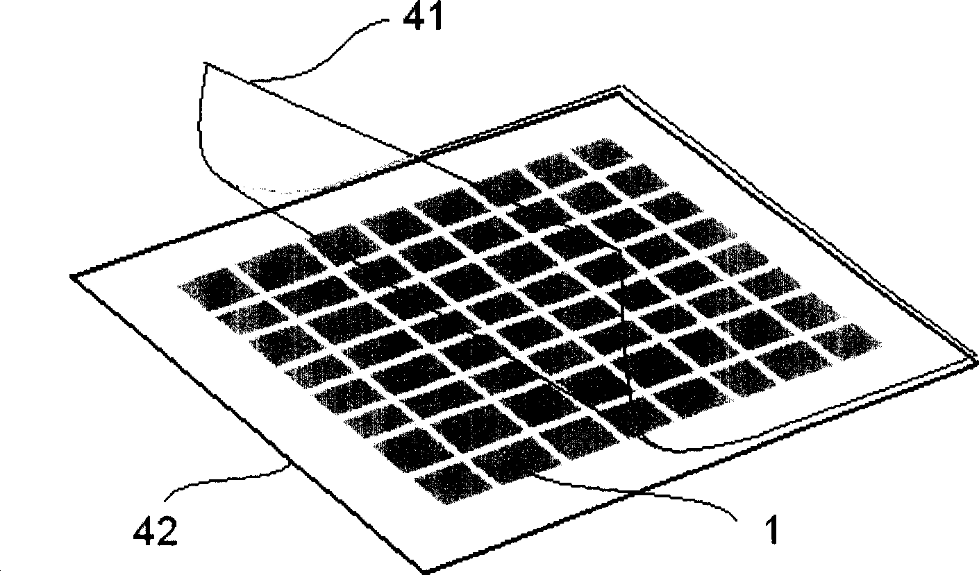
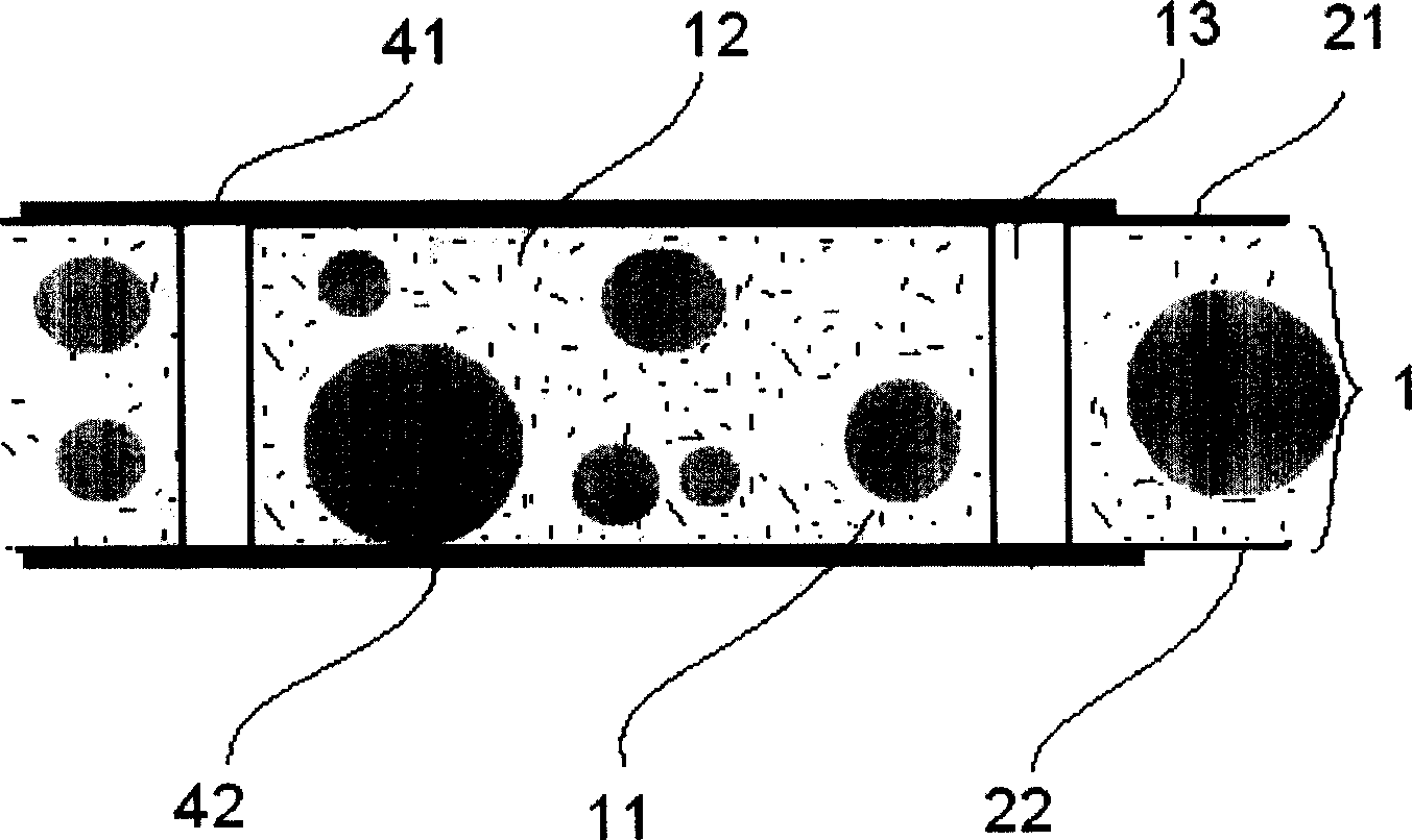
[0027] Embodiment of the soft heat conduction layer with checkerboard distribution of exhaust channels, such as Figure 4 shown. According to the roughness tolerance of the contact surface of the heating element and the heat dissipation element, the particles 11 with a specific size are mixed with the fluid plastic polymer material 12 to form a soft heat conduction layer 1 with a checkerboard-like distribution of exhaust channels. Both sides of the soft heat conduction layer are covered with release film protection. After tearing off the release film on the first side during use, attach this side of the soft heat conduction layer to the contact surface of the heating element or the contact surface of the heat dissipation element, and then Tear off the release film on the second surface, and press the heat conduction layer to the remaining contact surface of another component. When the soft heat-conducting layer is placed between the heating element and the heat-dissipating el...

Embodiment 2

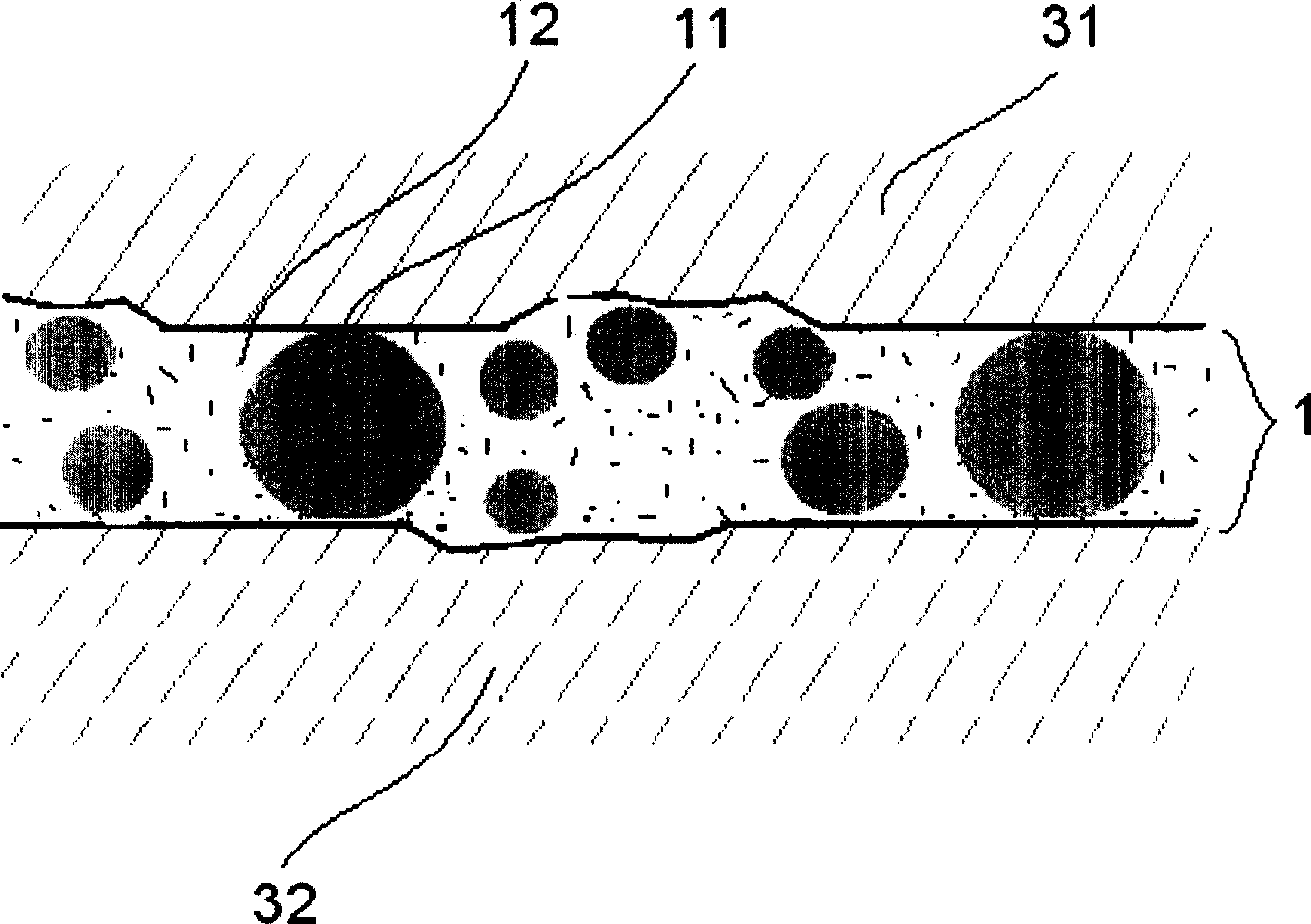
[0029] Examples of soft heat conduction layer for radially distributed exhaust passages, such as Figure 5 shown. According to the roughness tolerance of the contact surface of the heating element and the heat dissipation element, the particles 11 with a specific size are mixed with the fluid plastic polymer material 12 to form a soft heat conduction layer 1 with a checkerboard-like distribution of exhaust channels. The first side of the flexible heat conduction layer may not use the release film 41 on the first side, but directly use the screen printing method to place the structural material on the heat dissipation end surface in advance, and then cover the second side with a release paper for protection. When in use, the release film on the second surface is torn off, and pressed together with the remaining contact surface of another component. When the soft heat conduction layer is placed between the heating element and the heat dissipation element and is squeezed, the cl...


PUM


Abstract

The invention relates to a thermal conducive joint filling pad, with composite structure. Wherein, its soft thermal conductive layer is formed by mixed high-conductive power particles in certain granularity size and the macromolecule conjugation agent with plastic property; said layer is preset with ventilate channel; when the heating element and the heat emitter are compressed, the air inside the ventilate channel of soft thermal conducive layer between them will be discharged, and the plastic conductor will be filled, to confirm the thermal conducive effect; one or two surfaces of thermal conductive joint filling pad are coated with parting film; when the heating element and the heat emitter are compressed, the distance is reduced until they contact the largest thermal conductive particles, to form one uniform high-density thermal conductive layer.

Description

technical field [0001] The invention relates to a heat conduction gap filling material, in particular to a heat conduction gasket of a composite structure. Background technique [0002] As the chip rate and product power continue to increase, a large amount of heat needs to be discharged through the close contact between the surface of the heating element and the cooling element. However, due to factors such as processing roughness or tolerance, the contact surface of the heating element and the heat sink is not a true plane, and there is actually a certain gap between the two surfaces. The air in the gap is a poor thermal conductor with high thermal resistance, so the gap obviously becomes a place where heat is blocked and accumulated. [0003] There are three methods to solve this problem in the prior art: 1. Use a spatula to smear the heat dissipation paste whose main component is graphite or silica gel (SILICONE); 2. Use screen printing to apply the heat dissipation pas...

Claims


Application Information

Patent Timeline
IPC IPC(8): H05K7/20G12B15/06H01L23/42
Inventor 陈鸿文
Owner 陈鸿文
Why Eureka
Try Eureka