Cnt-based resistive heating for deicing composite structures

a composite structure and resistive heating technology, applied in the field of composite materials, can solve the problems of significant technical and safety concerns of the nacelle, difficult to effectively heat the external surface of the composite, and limited resistance heating

Active Publication Date: 2011-02-03
APPL NANOSTRUCTURED SOLUTIONS LLC
View PDF100 Cites 120 Cited by
  • Summary
  • Abstract
  • Description
  • Claims
  • Application Information

AI Technical Summary

Benefits of technology

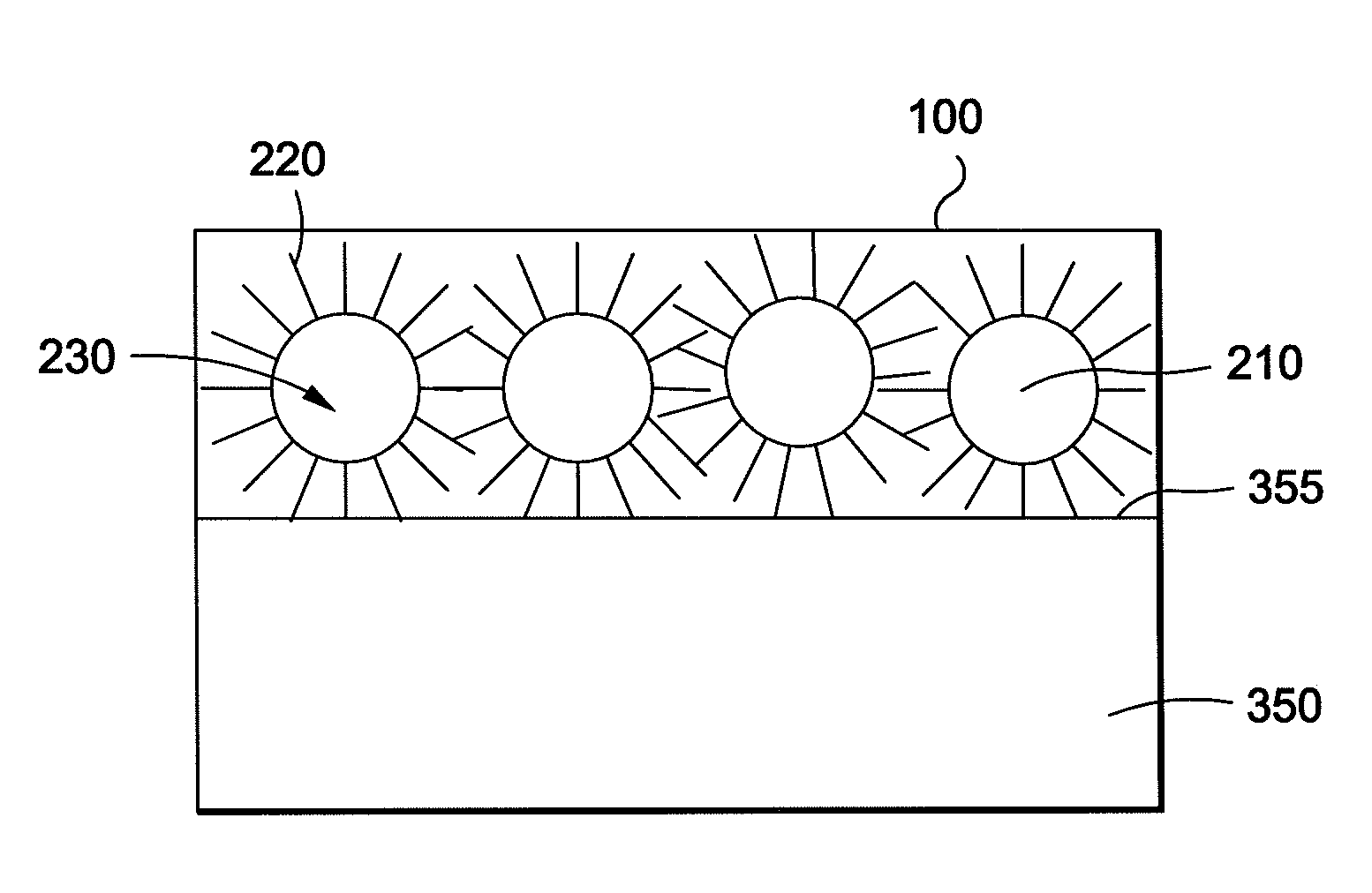
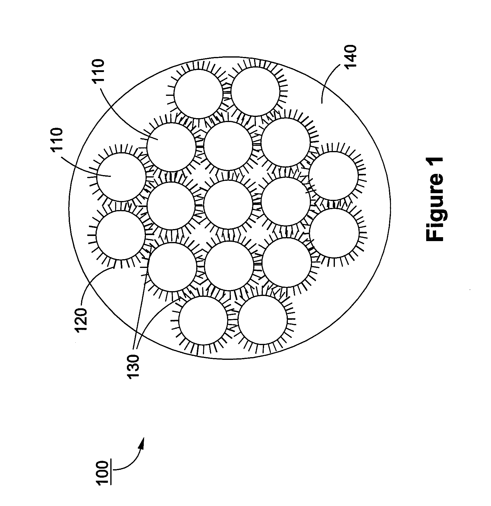
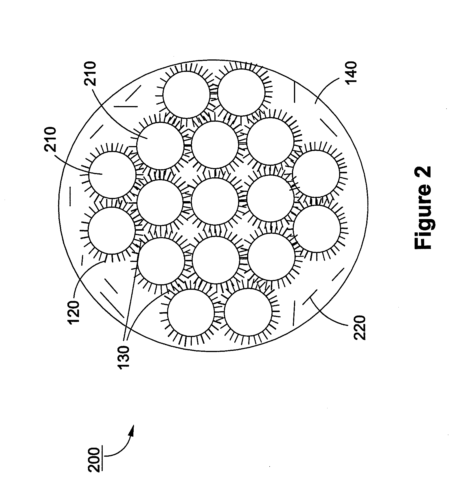
[0011]In some aspects, embodiments disclosed herein relate to a method of deicing or preventing ice formation on a surface of a composite structure that includes: a) providing a composite structure having CNT-infused fiber materials and b) applying a current to the CNT-infused fiber, thereby heating the composite structure.

Problems solved by technology

For example, the formation of ice on structures such as on leading edges of aircraft aerodynamic surfaces, such as wings, empennages or engine nacelles poses significant technical and safety concerns.
In this regard, it can be difficult to heat a composite external surface effectively due to poor heat transfer from imbedded heating devices to the surrounding composite material.
Thus, resistive heating has been limited due poor conducting properties of the composite materials.
However, such metal coatings incur increased cost and complexity due to the specialized manufacturing processes used to apply the coatings.
Moreover, the increased weight of the overall structure detracts from the advantage of provided by a composite structure.
Finally, such metal coatings are susceptible to galvanic corrosion making them susceptible to structural failures after repeated use.

Method used


Image

  • Cnt-based resistive heating for deicing composite structures
  • Cnt-based resistive heating for deicing composite structures
  • Cnt-based resistive heating for deicing composite structures

Examples


example i

[0153]This example shows how a carbon fiber material can be infused with CNTs in a continuous process to target thermal and electrical conductivity improvements for use in deicing applications.

[0154]In this example, the maximum loading of CNTs on fibers is targeted. 34-700 12 k carbon fiber tow with a tex value of 800 (Grafil Inc., Sacramento, Calif.) is implemented as the carbon fiber substrate. The individual filaments in this carbon fiber tow have a diameter of approximately 7 μm.

[0155]FIG. 12 depicts system 800 for producing CNT-infused fiber in accordance with the illustrative embodiment of the present invention. System 800 includes a carbon fiber material payout and tensioner station 805, sizing removal and fiber spreader station 810, plasma treatment station 815, barrier coating application station 820, air dry station 825, catalyst application station 830, solvent flash-off station 835, CNT-infusion station 840, fiber bundler station 845, and carbon fiber material uptake bob...


PUM

PropertyMeasurementUnit
lengthaaaaaaaaaa
lengthaaaaaaaaaa
lengthaaaaaaaaaa

Abstract

A composite structure includes a matrix material and a carbon nanotube (CNT)-infused fiber material that includes a plurality of carbon nanotubes (CNTs) infused to a fiber material. The CNT-infused fiber material is disposed throughout a portion of the matrix material. The composite structure is adapted for application of a current through the CNT-infused fiber material to provide heating of the composite structure. A heating element includes a CNT-infused fiber material includes a plurality of CNTs infused to a fiber material. The CNT-infused fiber material is of sufficient proportions to provide heating to a structure in need thereof.

Description

STATEMENT OF RELATED APPLICATIONS[0001]This application claims priority to U.S. Provisional Application Nos. 61 / 173,027, filed Apr., 27, 2009, and is incorporated herein by reference in its entirety.FIELD OF THE INVENTION[0002]The present invention relates to composite materials, more specifically to composite materials modified with carbon nanotubes.BACKGROUND OF THE INVENTION[0003]The increased exposure of composite materials to a wide range of environmental conditions has increased the demands placed on these materials. One such demand involves the deicing of composite structures. For example, the formation of ice on structures such as on leading edges of aircraft aerodynamic surfaces, such as wings, empennages or engine nacelles poses significant technical and safety concerns. A layer of ice as thin as one (1) millimeter (mm) may be sufficient to destabilize an in-flight aircraft.[0004]It has been indicated that to prevent against the formation of ice or to eliminate ice already...

Claims


Application Information

Patent Timeline
Patent Type & Authority Applications(United States)
IPC IPC(8): H05B3/02B32B5/16H05B3/10B82Y30/00
CPCB64D15/12Y10T428/25B82Y40/00C01B31/0233C01B31/0273C01B2202/02C01B2202/04C01B2202/06C01B2202/08C04B20/1014C04B20/1055C04B26/12C04B26/14C04B28/02C04B35/117C04B35/185C04B35/19C04B35/52C04B35/565C04B35/584C04B35/62873C04B35/62889C04B35/803C04B35/806C04B35/82C04B2111/00982C04B2111/90C04B2235/5224C04B2235/5236C04B2235/524C04B2235/5244C04B2235/5248C04B2235/526C04B2235/5264C04B2235/5288C22C47/02C22C49/14H05B2214/04B82Y30/00C04B14/386C04B14/42C01B32/162C01B32/174C04B35/80C01B32/16H05B3/145H05B2214/02
Inventor SHAH, TUSHAR K.MALECKI, HARRY C.ADCOCK, DANIEL JACOB
Owner APPL NANOSTRUCTURED SOLUTIONS LLC
Why Eureka
Try Eureka