

Mole cular sieve with composite structure and preparing method thereof
A technology of composite molecular sieve and composite structure, which is applied in the field of composite molecular sieve and its preparation, and can solve problems such as not very ideal
- Summary
- Abstract
- Description
- Claims
- Application Information
AI Technical Summary
Problems solved by technology
Method used
Image

Examples
preparation example Construction
[0056] In the process of preparing molecular sieves provided by the present invention, other raw materials and operating conditions can be determined according to the prior art, and IV in the said periodic table of the elements of general step (a) A Elemental compound, can be selected from one or more in the compound of silicon or germanium, preferably the compound of silicon, can be all silicon-containing compounds that can be used for preparing other molecular sieves, for example, active silicon dioxide, silicate, Silica sol and silicon-containing organic matter are preferably silicate, silica sol, and silicon-containing organic matter, more preferably silica sol. Said inorganic base can be all basic substances, such as hydroxides of alkali metals, carbonates, hydroxides of alkaline earth metals and ammonia water, etc., preferably hydroxides of alkali metals, more preferably potassium hydroxide . Said aluminum source can be one or more selected from activated alumina and it...
Embodiment 1
[0080] Using a gel of the same composition as described in Comparative Example 2, but adding 0.5 g of SiO 2 / Al 2 o 3 The molecular sieve with TON structure (0.06% relative to the weight of the gel) with a grain size of 44 and a grain size of 0.8 microns was used as a seed crystal, and after the same crystallization and post-treatment process as in Comparative Example 2, the sample number was obtained as E-1.
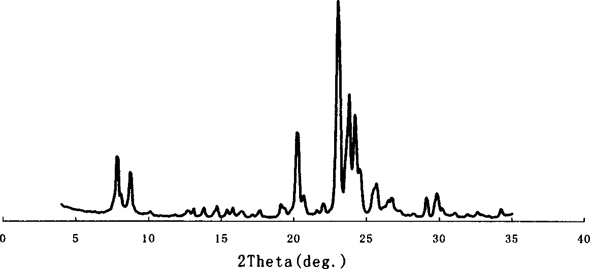
[0081] Characterization: SiO of sample E-1 2 / Al 2 o 3 58, the XRD results have the characteristics of Table 1 and Table 2, see Figure 4. It can be seen from Figure 4 that the product has the characteristics of TON and MFI structural molecular sieves, wherein the ratio of the content of TON structural molecular sieves to MFI structural molecular sieves is 2.0.
Embodiment 2
[0086] The preparation steps of molecular sieve mainly include:
[0087] (a) The preparation process of the gel is: the same as in Example 1, except adding 20.50 grams of 82% KOH, 25.3 grams of 1,8-octanediamine, 10 grams of Al 2 (SO 4 ) 3 .18H 2 O replaces 4 g of AlCl 3 , 5.8 grams of KF, 1.0 grams of TON molecular sieve (0.15w% relative to the weight of the gel) and 400 grams of water were mixed together in a certain order, and after 20 minutes of vigorous stirring, a uniform gel-like mixture was obtained, and the moles of the gel were obtained. Composed of:
[0088] 1.5K 2 O / 2.01R / 0.08Al 2 o 3 / 10SiO 2 / 1.0KF / 300H 2 o
[0089] R = 1,8-octanediamine
[0090] (b) crystallization process: same as embodiment 1.
[0091] (c) Post-treatment process: Same as in Example 1, the obtained sample number is E-2.
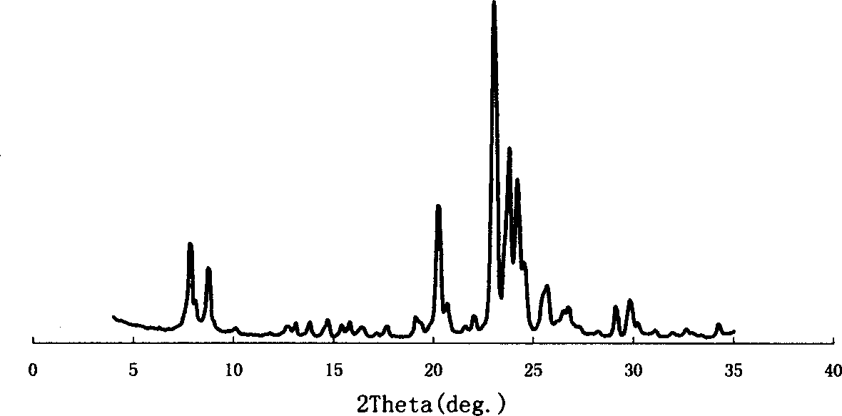
[0092] (d) Characterization: SiO of E-2 2 / Al 2 o 3 is 104, the XRD results of the sample have the characteristics of Table 1 and Table 2, see Figure 9. It can ...
PUM
 Abstract
Description
Claims
Application Information