Optical element using liquid crystal having optical isotropy
An optical element, isotropic technology, applied to the field of optical elements using optically isotropic liquid crystals, can solve problems such as slow response speed
- Summary
- Abstract
- Description
- Claims
- Application Information
AI Technical Summary
Problems solved by technology
Method used
Image
Examples
Embodiment approach 1
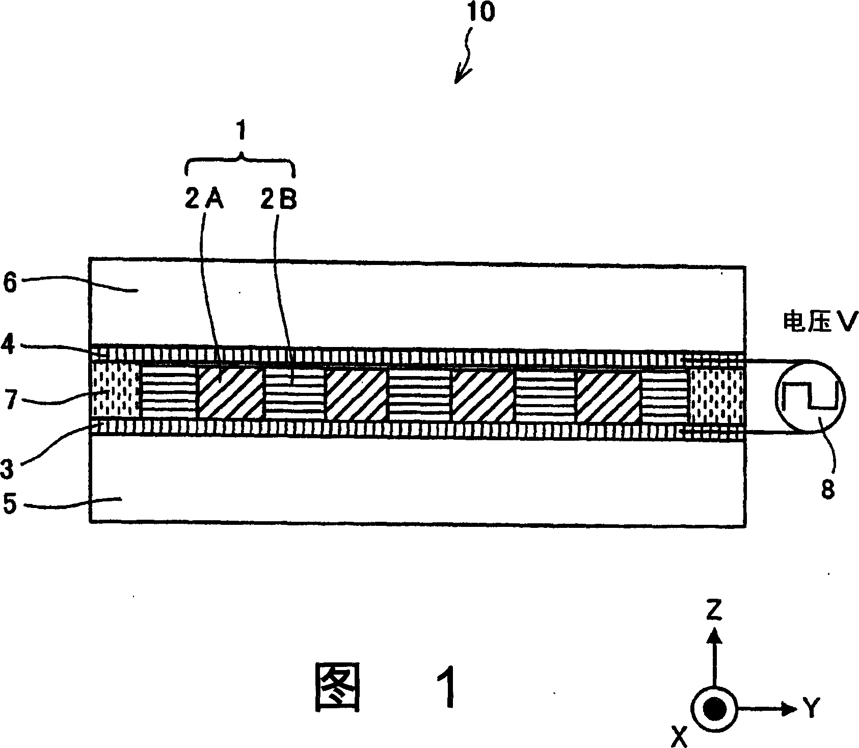
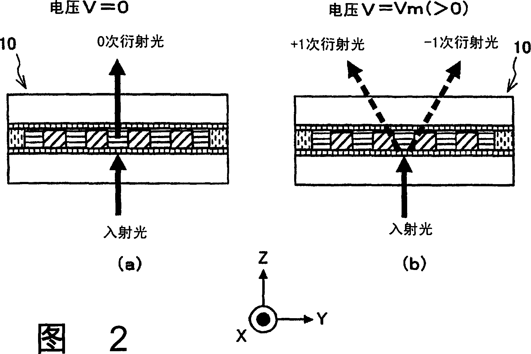
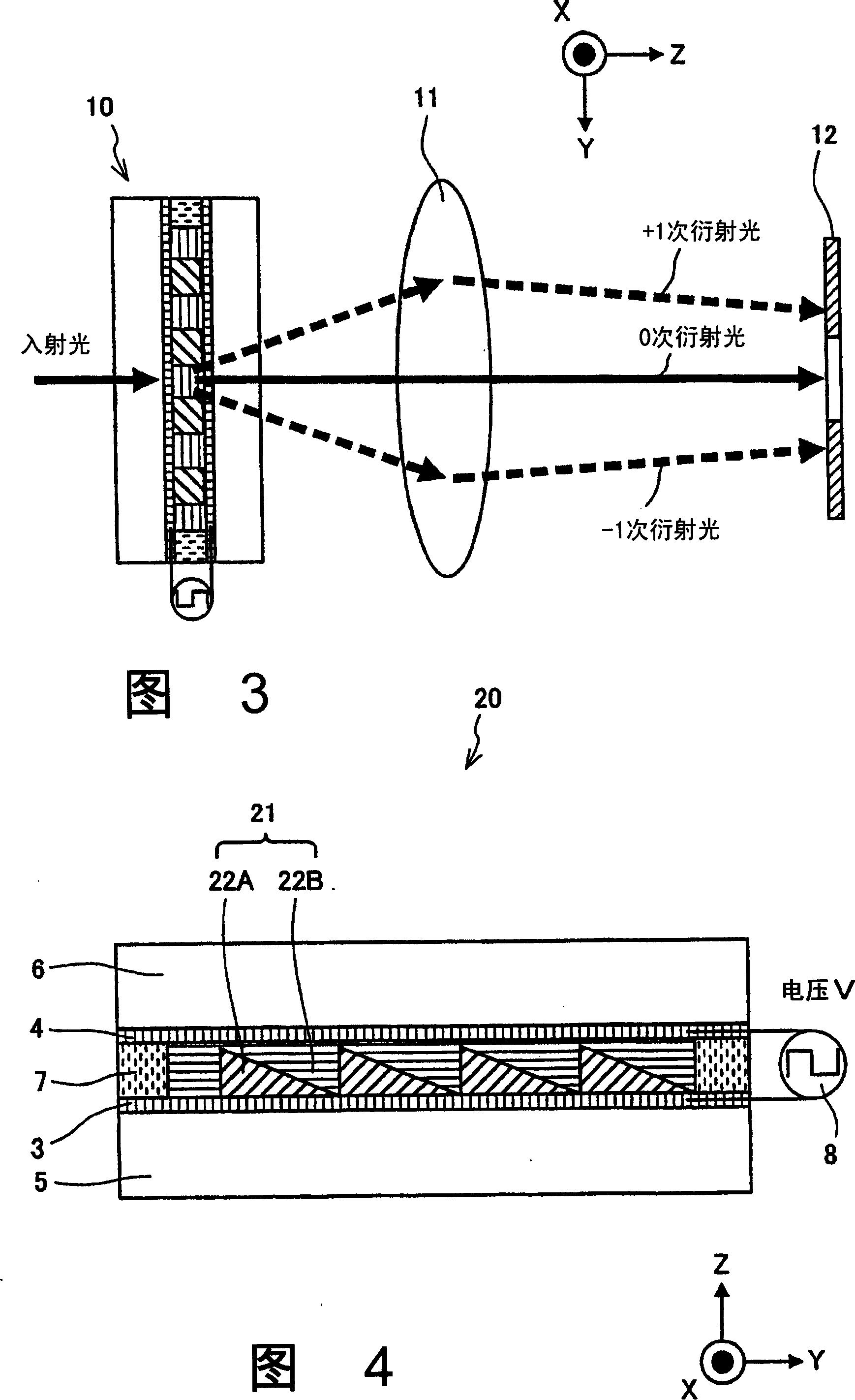
[0072]In Embodiment 1 of the present invention, a diffraction element and an optical attenuator are proposed and described as optical elements. FIG. 1 is a cross-sectional structural diagram conceptually showing a diffraction element according to Embodiment 1 of the present invention. In Fig. 1, the diffractive element 10 is constituted as follows: films of transparent electrodes 3, 4 are respectively formed on one surface of transparent substrates 5, 6, and each substantially rectangular parallelepiped is periodically arranged in parallel between the transparent electrodes 3, 4. The isotropic refractive index solid material forming the grid 2A, and the region between the isotropic refractive index solid material forming the grid 2A forms the diffraction grating 1 occupied by the isotropic refractive index liquid crystal 2B, formed by the transparent substrate 5 , 6 and sealing member 7 seal the isotropic refractive index liquid crystal 2B.
[0073] Here, the isotropic refrac...
Embodiment approach 2
[0099] In Embodiment 2 of the present invention, an element having a composition different from that of the diffraction element and the optical attenuator in Embodiment 1 is proposed and described as an optical element. Figure 8 is a cross-sectional view of a diffraction element according to Embodiment 2 of the present invention, Figure 9 is a top view of the diffraction element. In the diffraction element 40 according to Embodiment 2 of the present invention, transparent electrode 4 is removed from diffraction element 10 according to Embodiment 1 of the present invention, and patterned transparent electrodes 3A and 3B are provided instead of transparent electrode 3 .
[0100] Here, transparent electrodes 3A, 3B are formed so as to be sandwiched between transparent substrate 5 and grid 2A. The other components are the same as those of the diffraction element 10 according to Embodiment 1 of the present invention, and their descriptions are omitted. Therefore, the same compo...
Embodiment approach 3
[0108] In Embodiment 3 of the present invention, a variable wavelength filter is proposed as an optical element and described. Figure 10 It is a diagram showing a conceptual side cross-sectional structure of a variable wavelength filter according to Embodiment 3 of the present invention. Figure 10 Among them, the wavelength variable filter 50 is a filter called "liquid crystal standard type wavelength variable filter", which has a structure in which a pair of transparent substrates 56A and 56B are provided to face each other, and are substantially parallel to each other. A pair of reflective mirrors 53A and 53B forming an optical resonator, an isotropic refractive index liquid crystal 51 whose refractive index changes isotropically, and transparent electrodes 52A and 52B are arranged on transparent substrates 56A and 56B, and in 1 An isotropic refractive index liquid crystal 51 and a transparent and solid optical medium layer 58 (hereinafter, referred to as a solid optical m...
PUM
| Property | Measurement | Unit |
|---|---|---|
| Thickness | aaaaa | aaaaa |
Abstract
Description
Claims
Application Information
 - R&D
- Intellectual Property
- Life Sciences
- Materials
- Tech Scout
- Unparalleled Data Quality
- Higher Quality Content
- 60% Fewer Hallucinations
Browse by: Latest US Patents, China's latest patents, Technical Efficacy Thesaurus, Application Domain, Technology Topic, Popular Technical Reports.
© 2025 PatSnap. All rights reserved.Legal|Privacy policy|Modern Slavery Act Transparency Statement|Sitemap|About US| Contact US: help@patsnap.com


