Sintered body, magnetic head slider, and method of manufacturing sintered body

A manufacturing method and technology of sintered body, applied in the direction of nanotechnology, nanotechnology, nanotechnology, etc. for material and surface science, to achieve the effect of sufficient grinding speed and reducing step difference

Inactive Publication Date: 2007-01-10
TDK CORPARATION
View PDF2 Cites 0 Cited by
  • Summary
  • Abstract
  • Description
  • Claims
  • Application Information

AI Technical Summary

Problems solved by technology

As a result of research by the present inventors, it was found that the grinding speed of alumina-based sintered bodies such as aluminum-titanium-carbon sintered bodies and alumina-based sintered bodies conventionally used as substrates of magnetic head sliders is much lower than that of laminated bodies containing thin-film magnetic heads. Grinding speed, therefore, the grinding amount of the laminate is greater than that of the substrate during grinding, resulting in a larger step difference

Method used


Image

  • Sintered body, magnetic head slider, and method of manufacturing sintered body
  • Sintered body, magnetic head slider, and method of manufacturing sintered body
  • Sintered body, magnetic head slider, and method of manufacturing sintered body

Examples


Embodiment 1~3

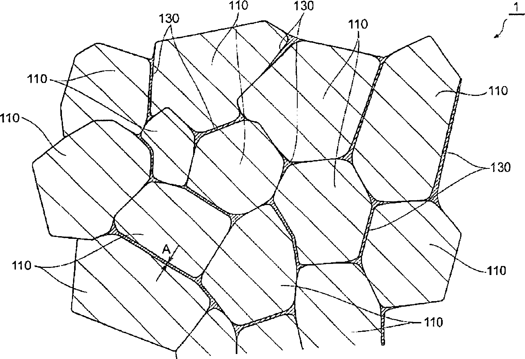
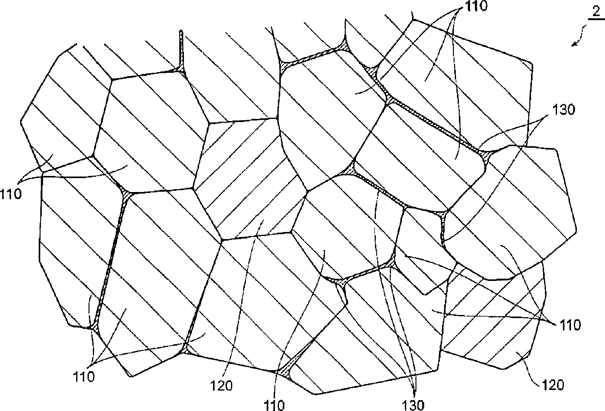
[0102] Weigh alumina powder (average particle size 320nm) and carbon powder (carbon black, average primary particle size 15nm) according to the specified amount respectively, pulverize together with IPA (isopropanol; boiling point 82.4°C) in a ball mill for 30 minutes and carry out After mixing, spray granulation was performed at 150° C. in nitrogen to obtain a granulated product.

[0103] Here, alumina powder and carbon powder were mixed in the granulated material at a concentration satisfying the following conditions. That is, when the weight of the alumina powder is 100 parts by weight, the weight of the carbon powder is 0.5 parts by weight in Example 1, 1.5 parts by weight in Example 2, and 3.1 parts by weight in Example 3.

[0104] Next, the obtained granules were heated at about 0.5MPa (50kgf / cm 2 ) under the pressure of a forming. Then, use the hot pressing method in a vacuum atmosphere and a spray pressure of about 30MPa (about 300kgf / cm 2 ) under sintering for 1 ho...

Embodiment 4~6

[0108] In Examples 4 to 6, except that carbon black having an average primary particle diameter of 100 nm was used as the carbon powder, the others were the same as in Comparative Examples 1 to 3.

Embodiment 7~9

[0112]In Examples 7 to 9, except that alumina powder, carbon powder, and titanium carbide powder (average primary particle size: 300 nm) were mixed, and the sintering temperature and mixing ratio were set as follows, the others were the same as in Example 1. In Example 7, when the weight of alumina powder is 100 parts by weight, the weight of carbon powder is 0.8 parts by weight, the weight of titanium carbide powder is 56.3 parts by weight, and the sintering temperature is 1700°C. In Example 8, the weight of carbon powder is 2.3 parts by weight, the weight of titanium carbide powder is 56.3 parts by weight, and the sintering temperature is 1720°C. In Example 9, the weight of carbon powder is 4.0 parts by weight, the weight of titanium carbide powder is 56.2 parts by weight, and the sintering temperature is 1720°C. In addition, about 0.1% of carbon based on the weight of titanium carbide is unavoidably contained in the titanium carbide powder, but since the amount is small, it...


PUM

PropertyMeasurementUnit
diameteraaaaaaaaaa
thicknessaaaaaaaaaa
particle diameteraaaaaaaaaa

Abstract

The present invention provides a sintered body for a magnetic head slider that reduces the step of an air bearing surface and has high strength, a magnetic head slider using the sintered body, and a method for manufacturing the sintered body for a magnetic head slider. The sintered body of the present invention is a sintered body having alumina crystal grains 110 and a carbon-containing thin film 130 existing at grain boundaries between the alumina crystal grains 110, and the average particle diameter of the alumina crystal grains 110 is 0.05 to 0.5 μm.

Description

technical field [0001] The present invention relates to a sintered body, a magnetic head slider, and a method for manufacturing the sintered body. Background technique [0002] A magnetic head slider including a thin-film magnetic head was first used in a hard disk device in 1979, but the magnetic head slider at that time was generally called a mini-slider (100% slider). Afterwards, the magnetic head slider has developed into a nano-slider (Nano-Slider, 70% slider), which is about 50% of the size of the miniature slider, through a micro-slider (Micro-Slider, 70% slider), which is about 70% of the size of the miniature slider. 50% slider) towards miniaturization. [0003] This magnetic head slider generally has a laminated body including a thin film magnetic head on an alumina substrate. Such a magnetic head slider is obtained by laminating a laminated body including a thin-film magnetic head on a substrate to form a laminated structure, and then cutting the laminated struc...

Claims


Application Information

Patent Timeline
Patent Type & Authority Applications(China)
IPC IPC(8): C04B35/00C04B35/10C04B35/622
CPCC04B2235/3843C04B2235/5445C04B35/62655C04B2235/85C04B2235/3232C04B2235/963C04B2235/422C04B2235/5454C04B2235/549C04B2235/77C04B2235/781C04B2235/786C04B35/62695C04B35/645C04B2235/656C04B35/117C04B2235/785B82Y30/00
Inventor 人见笃志久保启子川口行雄杉浦启桑原恒男
Owner TDK CORPARATION
Why Eureka
Try Eureka