Part mounting head, pick-up nozzle, pick-up nozzle manufacturing method

A manufacturing method and a technology for installing heads, which are applied in the direction of manufacturing tools, chucks, electrical components, etc., can solve the problems of component pollution, component damage, damage, etc., and achieve the effect of preventing pollution and preventing electrical damage

Active Publication Date: 2007-01-10
PANASONIC CORP
View PDF2 Cites 5 Cited by
  • Summary
  • Abstract
  • Description
  • Claims
  • Application Information

AI Technical Summary

Problems solved by technology

[0014] However, in a suction nozzle formed of a ceramic material as described in JP-A-2000-151200, since the ceramic material is generally an electrical insulating material, static electricity is likely to be generated in the suction nozzle main body, thereby causing The static electricity may induce dust, etc. to adhere to the suction nozzle, and the suction nozzle itself or even the parts held by suction may be contaminated.
In addition, since this kind of static electricity is transferred to the components during adsorption and holding, there is a possibility of damaging the components that are held by adsorption or that are in contact with the adsorption nozzle.
In this case, it is not only impossible to carry out reliable and stable adsorption and holding of parts, but also there is a problem of contamination or destruction of the held parts.
[0015] In addition, when the adsorption nozzle 114 described in JP-A-2002-233983 is formed of a conductive material instead of an electrically insulating material, the member to be adsorbed and held by the adsorption nozzle 114 There may be electricity between the suction nozzle 114, in this case, the parts will be damaged
In particular, this problem becomes more pronounced when the component is made vulnerable to electrical loads due to the high functionality of the component.
[0016] In addition, in this adsorption nozzle 114, in order to cope with the diversification of components, especially in order to cope with the adsorption and holding of large components such as QFP, the adsorption nozzle 114 is equipped with a pad portion 122 formed of a soft elastic body. The front end portion of the skirt portion 171 of 122 is located below the suction surface of the suction nozzle 114, for example, in the case of suctioning and holding a component whose surface to be adsorbed is small and extends to the pad portion 122 as a whole. , the liner portion 122 is in contact with the component prior to the suction surface, and thereafter, the skirt 171 is pushed by the component to deform elastically. Although the suction surface is in contact with the component, the skirt 171 is in the elastically deformed state , so the force that pulls the contact state between the adsorption surface and the component will act, so that it may not be possible to obtain sufficient adsorption and retention force formed by the adsorption surface
In this case, there is a problem that it is impossible to flexibly cope with the adsorption and retention of parts with various shapes that have been diversified.

Method used


Image

  • Part mounting head, pick-up nozzle, pick-up nozzle manufacturing method
  • Part mounting head, pick-up nozzle, pick-up nozzle manufacturing method
  • Part mounting head, pick-up nozzle, pick-up nozzle manufacturing method

Examples


Embodiment Construction

[0072] Embodiments of the present invention will be described in detail below based on the drawings.

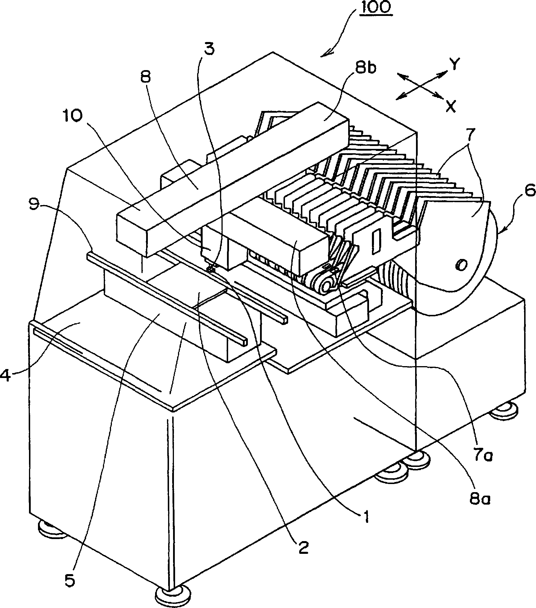
[0073] exist figure 1 A schematic perspective view showing a schematic configuration of a component mounting apparatus 100 including the component mounting head 10 according to Embodiment 1 of the present invention is shown in .

[0074] Such as figure 1 As shown, the component mounting apparatus 100 includes: a component supply device 6 as an example of a component supply unit, which can supply a plurality of components 1; a stage 5 as an example of a substrate holding unit, which mounts the The substrate 2 of each component 1 to be supplied can be held releasably; the mounting head 10, which will be held and taken out by each component 1 supplied releasably from the component supply part 6, and placed on the substrate 2 held by the stage 5 Mounting of the held components 1 is performed; an XY robot 8 as an example of a head moving device performs a movement operation of...


PUM

PropertyMeasurementUnit
electrical resistivityaaaaaaaaaa
particle diameteraaaaaaaaaa
diameteraaaaaaaaaa

Abstract

The present invention provides a component mounting head in which the suction and holding surface (14) of a component (1) of a suction nozzle (3) is formed of semiconducting ceramics, so that the component is in direct contact with the component during suction and holding. The suction holding surface has the characteristics of being a semiconductor, thereby preventing the disadvantages accompanying the generation of static electricity in the suction nozzle and the disadvantages accompanying the suction nozzle and the member being brought into an electrically conductive state .

Description

technical field [0001] The present invention relates to a component mounting head, a suction nozzle, and a component mounting head for mounting a component on a substrate by arranging it at a component mounting position on a substrate to release suction and holding the component by sucking and holding it with a suction nozzle. How the mouth is made. Background technique [0002] Conventionally, a component mounting apparatus provided with such a component mounting head equipped with suction nozzles is configured such that the components to be mounted on the substrate are positioned so that the suction nozzles are positioned above the components to be mounted on the substrate. The mounting head relatively moves with respect to the component, and thereafter, by lowering the suction nozzle, the component is brought into contact with the suction holding surface of the suction nozzle, and by attracting the component with the suction holding surface, The suction holding of the co...

Claims


Application Information

Patent Timeline
Patent Type & Authority Applications(China)
IPC IPC(8): B25J15/06H05K13/04
CPCY10T29/53178H05K13/0408Y10T29/53174Y10T29/53191H05K13/0409H05K13/04
Inventor 内田英树樱井利沙远藤真一郎城户一夫
Owner PANASONIC CORP
Why Eureka
Try Eureka