Supercharge Your Innovation With Domain-Expert AI Agents!

Processor, multiprocessor system, processor system, information processing device, and temperature control method

A multi-processor system and processor technology, applied in multi-programming devices, machine execution devices, program control design, etc., can solve the problems of reducing the operating frequency of the chip, sacrificing the processing performance of the processor, and poor time responsiveness.

Inactive Publication Date: 2007-01-10
SONY COMPUTER ENTERTAINMENT INC
View PDF1 Cites 7 Cited by
  • Summary
  • Abstract
  • Description
  • Claims
  • Application Information

AI Technical Summary

Problems solved by technology

Conventional heat generation countermeasures are to macroscopically observe the temperature distribution of the entire chip and spend a few seconds to a minute to dissipate heat, and the time response is not good.
In the recent highly integrated LSI, a chip is designed that consumes about tens of watts of power in one chip. If the heat release process is not performed with an instruction of tens of microseconds, it will cause malfunction due to a sharp temperature rise.
Although heat is generated locally, when the temperature of the entire chip is at a safe temperature, if the operating frequency of the chip is lowered, the overall processing performance of the processor will be sacrificed, which is inefficient.

Method used


Image

  • Processor, multiprocessor system, processor system, information processing device, and temperature control method
  • Processor, multiprocessor system, processor system, information processing device, and temperature control method
  • Processor, multiprocessor system, processor system, information processing device, and temperature control method

Examples


Embodiment approach 1

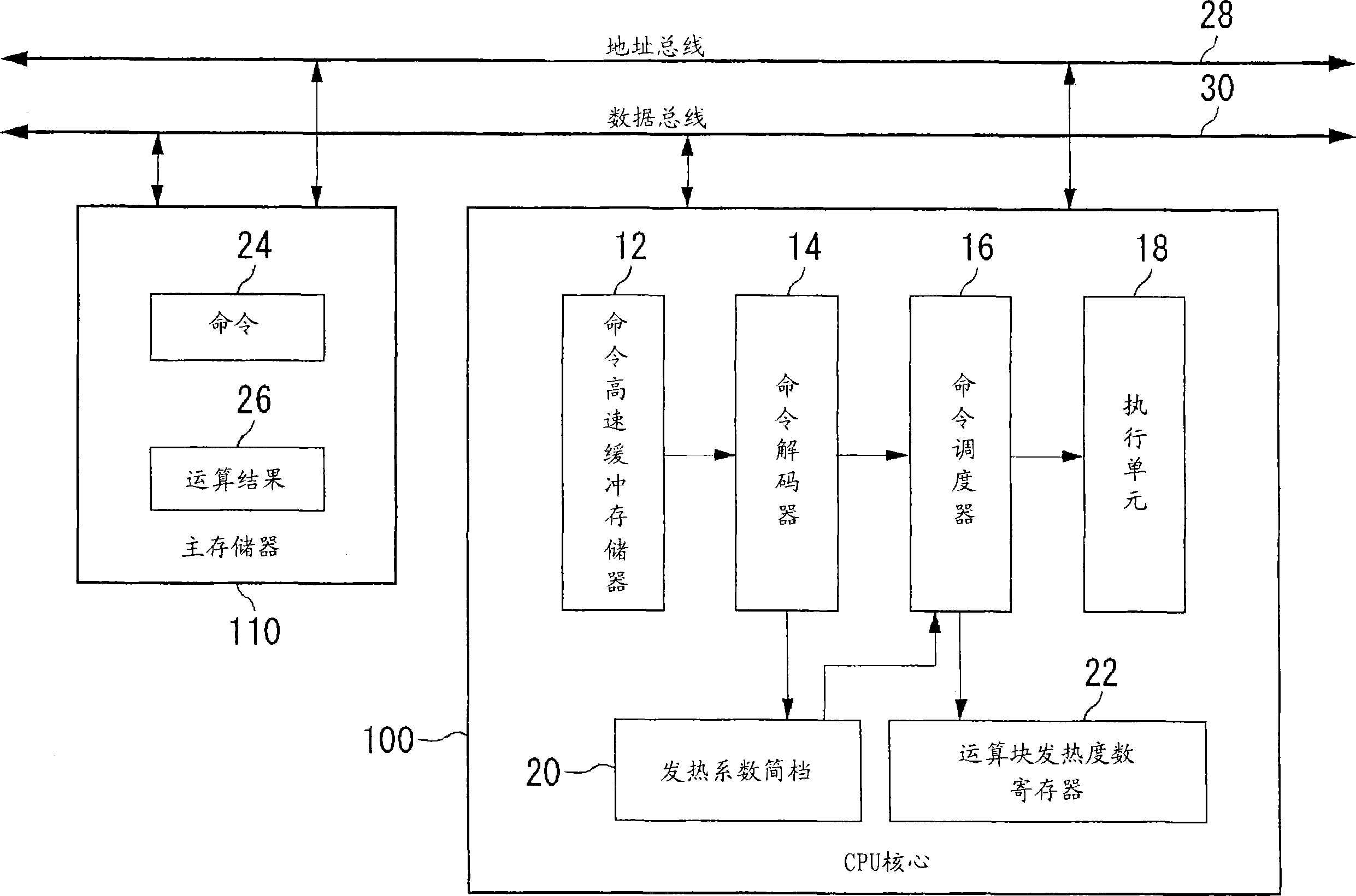
[0029] figure 1 It is a block diagram of the processor system of Embodiment 1. The processor system includes a CPU core 100 , a main memory 110 , which are connected to an address bus 28 and a data bus 30 . The CPU core 100 specifies an address to the main memory 110 to read and write data. The CPU core 100 includes a command cache memory 12 , a command decoder 14 , a command scheduler 16 , an execution unit 18 , a thermal coefficient profile 20 , and a calculation block thermal degree register 22 . Instructions 24 and calculation results 26 are stored in main memory 110 .

[0030] The command 24 read out from the main memory 110 by the CPU core 100 is temporarily cached in the command cache memory 12 . The command decoder 14 sequentially decodes the commands 24 cached in the command cache 12 and provides them to the command scheduler 16 . The command scheduler 16 arranges and replaces the order of execution of the commands 24 and adjusts the execution timing according to ...

Embodiment approach 2

[0054] Figure 6 It is a block diagram of the processor system of Embodiment 2. The processor system of the present embodiment is a multiprocessor system in which two subprocessors 230a, 230b are bus-bonded, in addition to the main processor 200 corresponding to the CPU core 100 of the first embodiment. The main processor 200 accesses the DRAM 220 via the bus to read data, and caches the data in the cache memory 210 . The main processor 200 appropriately assigns tasks to the two sub-processors 230a and 230b to execute programs.

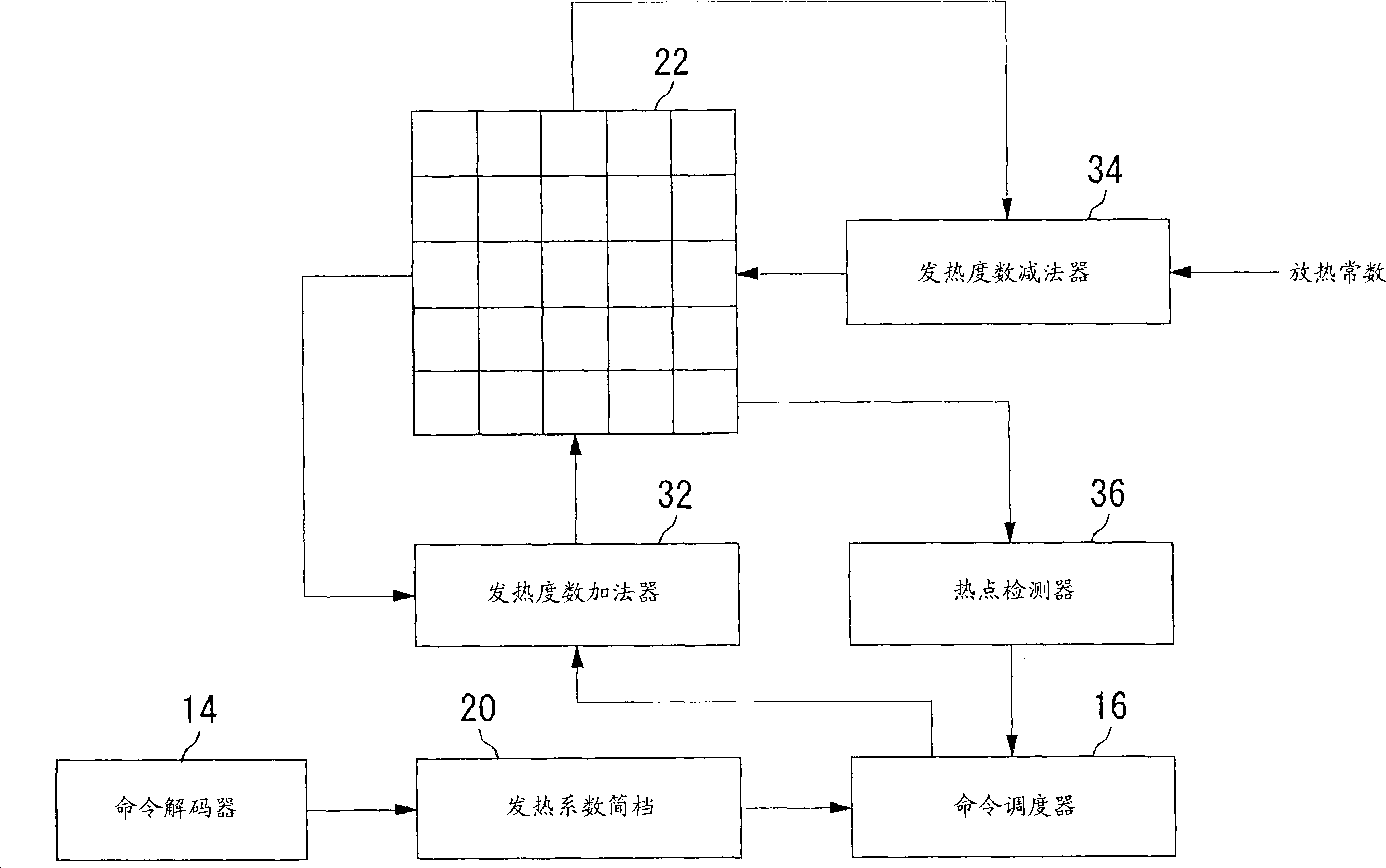
[0055] The main processor 200 includes each functional structure of the CPU core 100 described in Embodiment 1, that is, the command cache 12, the command decoder 14, the command scheduler 16, the execution unit 18, the thermal coefficient profile 20, the calculation Block heat degree register 22 , heat degree adder 32 , heat degree subtractor 34 and hot spot detector 36 . Hereinafter, operations different from those of the first embodiment will be...


PUM


Abstract

An instruction decoder 14 identifies, for each instruction, an operational block involved in the execution of the instruction and an associated heat release coefficient. The instruction decoder stores identified information in a heat release coefficient profile 20. An instruction scheduler 16 schedules the instructions in accordance with the dependence of the instructions on data. A heat release frequency adder 32 cumulatively adds the heat release coefficient to the heat release frequency of the operational block held in the operational block heat release frequency register 22 as the execution of the scheduled instructions proceeds. A heat release frequency subtractor 34 subtracts from the heat release frequency of the operational blocks in the operational block heat release frequency register 22 in accordance with heat discharge that occurs with time. A hot spot detector 36 detects an operational block with its heat release frequency, held in the operational block heat release frequency register 22, exceeding a predetermined threshold value as a hot spot. The instruction scheduler 16 delays the execution of the instruction involving for its execution the operational block identified as a hot spot.

Description

technical field [0001] The invention relates to processor technology, in particular to a processor capable of controlling heat generation, a multi-processor system, a processor system, an information processing device and a temperature control method. Background technique [0002] In LSI design, the miniaturization of the manufacturing process and the high integration of components are further progressing, and it is very important to consider the heat generation as the performance limit of the chip in the design. When the chip is at a high temperature, it will cause malfunction or lower long-term reliability, so various heat generation countermeasures are taken. For example, a cooling fan is provided above the chip to dissipate heat generated from the chip. [0003] Furthermore, since the distribution of power consumption on the chip is not uniform, the problem of a so-called "hot spot" in which a part of the chip becomes abnormally high in temperature cannot be avoided. T...

Claims


Application Information

Patent Timeline
Patent Type & Authority Applications(China)
IPC IPC(8): G06F9/50G06F9/30G06F9/32G06F1/00G06F1/20G06F1/32G06F9/38G06F9/46G06F15/177
CPCG06F9/3836G06F1/206G06F1/3203Y02B60/144G06F9/4881G06F1/329G06F9/3869G06F9/505Y02B60/1217Y02D10/00G06F1/00G06F9/30G06F9/46G06F9/50
Inventor 安达健一矢泽和明泷口岩今井敦彦田村哲司
Owner SONY COMPUTER ENTERTAINMENT INC
Features
  • R&D
  • Intellectual Property
  • Life Sciences
  • Materials
  • Tech Scout
  • Unparalleled Data Quality
  • Higher Quality Content
  • 60% Fewer Hallucinations
Learn More