Micro air bubble generation device and method, water treatment device using the same

A technology of water treatment equipment and generation device, which is applied in the direction of oxidized water/sewage treatment, etc., can solve the problems of water treatment methods, changes in decompression, and changes in ozone dissolution efficiency without revealing the generation method of micro bubbles, so as to maintain the ozone dissolution efficiency , Improve the operation economy and improve the effect of water treatment capacity

Inactive Publication Date: 2007-01-24
HITACHI LTD
View PDF9 Cites 22 Cited by
  • Summary
  • Abstract
  • Description
  • Claims
  • Application Information

AI Technical Summary

Problems solved by technology

[0013] In the prior art described in Non-Patent Document 1, the characteristics of microbubbles are described, but the generation method of microbubbles and the specific water treatment method are not disclosed.
In addition, the prior art described in Non-Patent Document 2 is a method of generating air bubbles by shearing the impeller of the pump. In this air bubble generation method, there is a problem that the air bubbles are not fine enough.
[0014] In the prior art described in Patent Document 1, the mixed water is pressurized by a high-pressure pump on the upstream side of the orifice, and is decompressed when passing through the orifice, so that tiny air bubbles can be generated. However, due to the flow path area of ​​the orifice It is fixed, so when it is necessary to change the necessary flow rate of the mixed water with ozone micro-bubbles, there is a problem that this requirement cannot be met
In addition, when the pressurized pressure changes, the diameter and the amount of generation of micro-bubbles also change, so the ozone dissolution efficiency changes and the water treatment capacity becomes unstable.
When changing the pressurized pressure and flow rate in this way, it is possible to provide a bypass flow path with a flow rate adjustment valve in the high-pressure pump and let a part of the mixed water pass through the bypass flow path. The mixed water flowing through the flow path is not sent to the orifice, but is wasted, increasing the loss of power supplied to the high-pressure pump
[0015] In the prior art described in Patent Document 2, the pressurization pressure of the orifice is controlled by adjusting the rotational speed of the pump with an inverter. However, since the flow path area of ​​the orifice is fixed, the Therefore, when the required flow rate of water mixed with ozone microbubbles changes, the pressurized pressure will change, and microbubbles cannot be stably generated.
[0016] In the prior art described in Patent Document 3, the throttling of the flow path of the orifice can be adjusted, so that the pressurized pressure can be controlled. According to this method, although the flow rate of the water mixed with ozone microbubbles can also be controlled, when throttling When the flow path restriction of the hole changes, the flow velocity when passing through the orifice changes, and the decompression amount of the orifice portion for generating microbubbles also changes.
Therefore, when the balance of pressurization and decompression changes, the diameter and generation amount of microbubbles also change, so the ozone dissolution efficiency changes, and the water treatment capacity becomes unstable.

Method used


Image

  • Micro air bubble generation device and method, water treatment device using the same
  • Micro air bubble generation device and method, water treatment device using the same
  • Micro air bubble generation device and method, water treatment device using the same

Examples


Embodiment 1

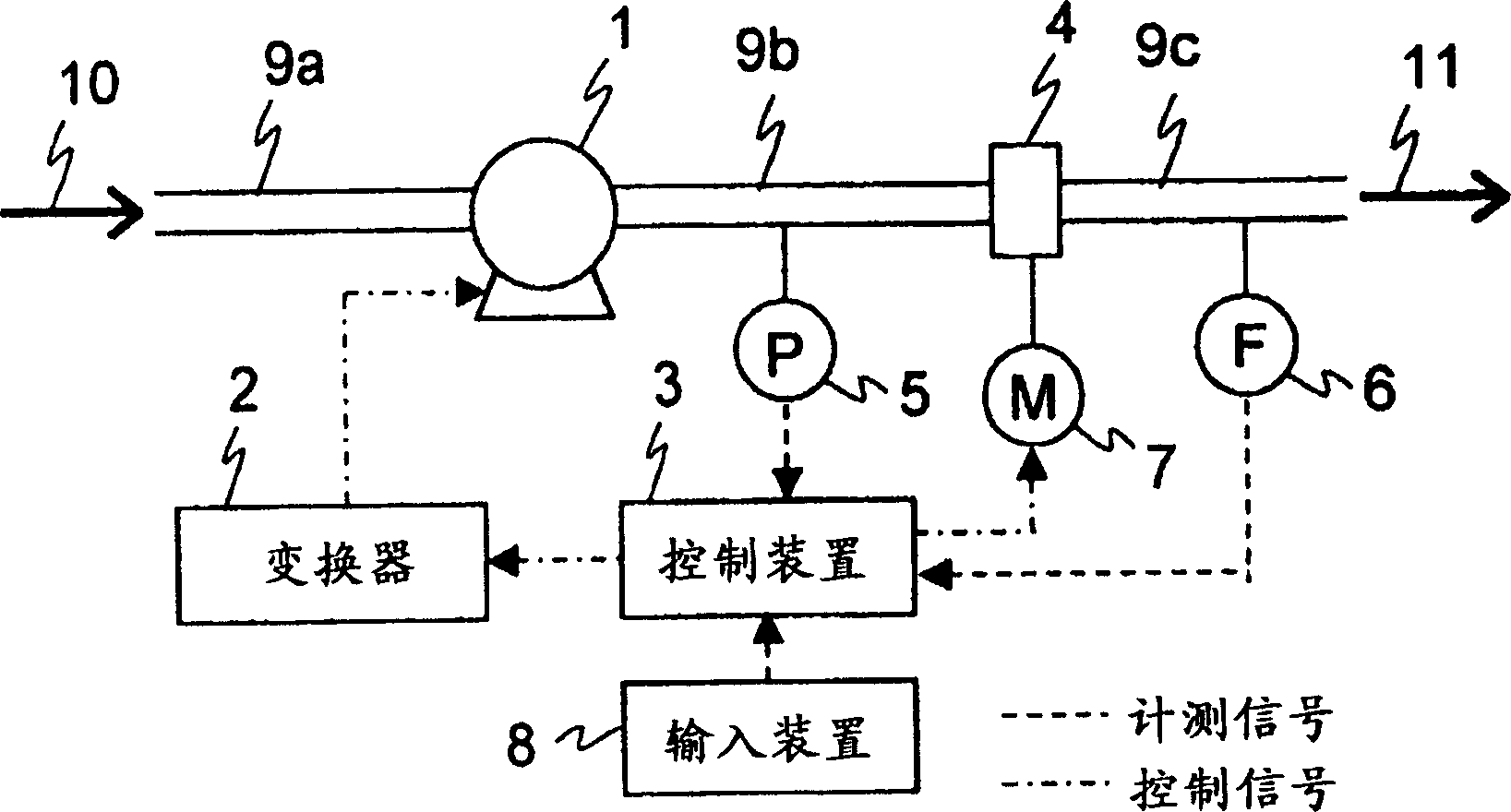
[0089] Below, refer to Figure 1 to Figure 12 Example 1 of the present invention will be described. figure 1 It is a configuration diagram of the microbubble generating device of this embodiment.

[0090] The micro-bubble generating device of the present embodiment, such as figure 1 As shown, the flow path 9a connected to the gas-liquid two-phase flow generating device not shown, the pump 1 connected to the flow path 9a, the converter not shown connected to the pump 1, the flow path 9b and the The perforated plate assembly 4 connected to the pump 1, the pressure gauge 5 provided on the flow path 9b, the driving device 7 provided on the perforated plate assembly 4, the flow path 9c connected to the perforated plate assembly 4, the pressure gauge 5 provided on the flow path 9c The flow meter 6 above, the control device 3, and the input device 8 connected to the control device 3 constitute. Here, in the gas-liquid two-phase flow, the liquid is water, and the gas is any one of ...

Embodiment 2

[0119] Below, refer to Figure 13 to Figure 16 Example 2 of the present invention will be described. Figure 13 It is a configuration diagram of the microbubble generating device of this embodiment.

[0120]The microbubble generator of this example is configured in the same manner as in Example 1, however, in this example, a porous plate assembly 40 is used instead of the porous plate assembly 4 . The structure of the perforated plate assembly 40 is that, behind the pump 1 in the flow path 9b, several branch flow paths are provided, and the porous plates 40 respectively having a fixed number of holes are arranged on each branch flow path through valves 70-1 to 70-n. -1~40-n. The plurality of porous plates 40-1 to 40-n are connected to the flow path 9c after merging. The valves 70-1 to 70-n are respectively connected to the control device 3 through signal lines, and the opening and closing of the valves 70-1 to 70-n are controlled. Here, in the case where the flow path 9c c...

Embodiment 3

[0133] Below, refer to Figure 17 to Figure 23 Embodiment 3 of the present invention will be described. Figure 17 to Figure 23 is a configuration diagram of the perforated plate assembly in this example.

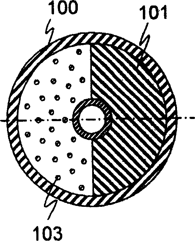
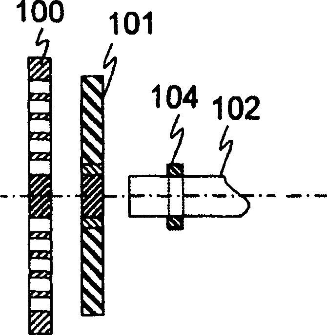
[0134] The perforated plate assembly of this embodiment is the one in Example 1 Figure 2 to Figure 6 A variation of the perforated plate assembly 4 is shown.

[0135] Such as Figure 17 to Figure 23 As shown in the perforated plate 210, the circular plate is divided into several regions, and holes with different pore diameters are formed in each region, that is, holes with different cross-sectional areas are provided in each region. Alternatively, holes of the same cross-sectional area may be provided in each region of the porous plate 210 so that the holes have the same diameter and the number of holes per unit surface area is different. The flow path restricting plates are arranged on both sides of the porous plate 210, the semicircular flow path restricting plate 21...


PUM


Abstract

The invention provides an apparatus and a method for producing microbubbles. Fluid in which gas is dissolved under pressure with a pump 1 flows into a porous plate unit 4 and when passing through the porous plate, the fluid is decompressed and dissolved gas is deposited to form microbubbles. A controller 3 changes rotational frequency of the pump 1 via an inverter 2 to control an ejection flow rate of microbubble-containing water 11. At the same time, the controller 3 changes the number of pores in a narrow flow passage via a driving gear 7 to keep pressurizing pressure above a minimum value of pressure required for producing microbubbles and below a predetermined maximum value.

Description

technical field [0001] The present invention relates to a micro-bubble generating device and method for stabilizing the diameter and amount of micro-bubbles, and a water treatment device using micro-bubbles that can be used for purification, sterilization, and disinfection of tap water, sewer water, river water, lake water, and industrial drainage. . Background technique [0002] Non-Patent Document 1 describes the use and effects of microbubbles in purification, sterilization, and disinfection. In addition, Non-Patent Document 2 describes the bactericidal effect of ozone water. In the description of Non-Patent Document 1, microbubbles are bubbles with a diameter of 50 micrometers or less called microbubbles. Generally, for bubbles in this diameter range, the gas in the bubbles dissolves into the surrounding liquid phase, and the diameter decreases. Therefore, under the action of surface tension, the internal components are in a state of high pressure and high temperature,...

Claims


Application Information

Patent Timeline
Patent Type & Authority Applications(China)
IPC IPC(8): C02F1/78
Inventor 隅仓岬日高政隆渡边昭二芳贺铁郎圆佛伊智朗原直树
Owner HITACHI LTD
Why Eureka
Try Eureka