Three terminal type magnetic flow gate sensor

A fluxgate sensor and sensor technology, which is applied to the magnetic field measurement and the size/direction of the magnetic field using the principle of magnetic flux control, and can solve the problems of inconvenient winding of the measuring coil, poor noise, and large excitation power consumption.

Inactive Publication Date: 2007-01-31
SHANGHAI MARITIME UNIVERSITY
View PDF0 Cites 7 Cited by
  • Summary
  • Abstract
  • Description
  • Claims
  • Application Information

AI Technical Summary

Problems solved by technology

When the four-terminal racetrack-shaped fluxgate sensor is manufactured, it is inconvenient to pass through the core of the measuring coil, and the excitation voltage requires stable

Method used


Image

  • Three terminal type magnetic flow gate sensor
  • Three terminal type magnetic flow gate sensor
  • Three terminal type magnetic flow gate sensor

Examples


Embodiment Construction

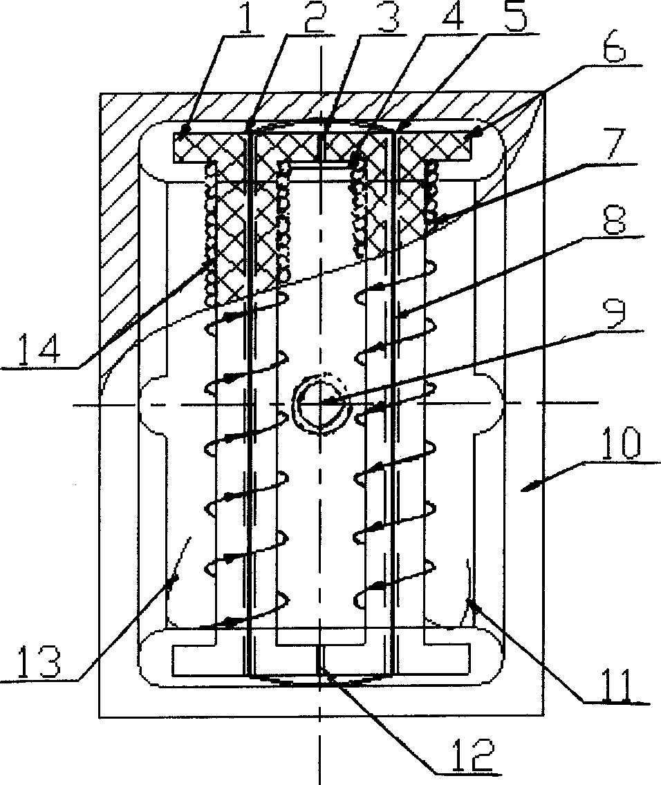
[0016] The present invention will be described in further detail below in conjunction with the accompanying drawings.

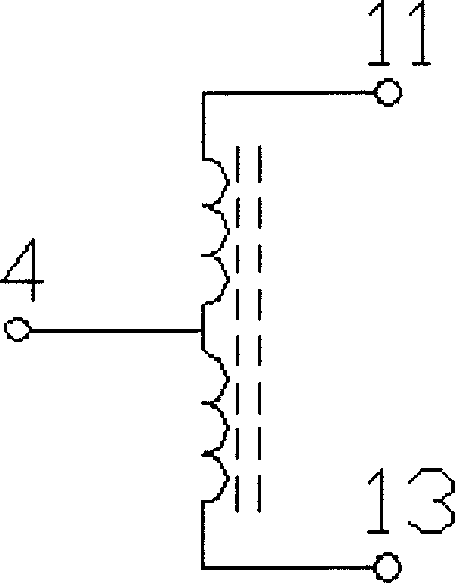
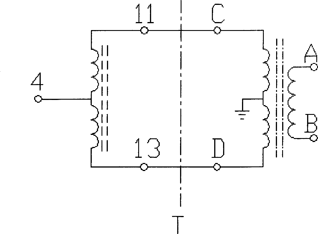
[0017] see figure 1 , 1 and 6 are "I"-shaped ceramic skeletons, 14 and 7 are two sets of coils tightly and evenly wound on the skeletons 1 and 6, and 800 to 1000 turns are wound with φ0.1 enameled wire, and the winding direction of the coils is as shown by the arrow. 13 is the starting end of the coil 14, and 11 is the end of the coil 7. The end of the coil 14 and the beginning of the coil 7 are connected to form the central end 4. 3 and 12 are the two joints of the "I"-shaped ceramic skeleton 1 and 6, forming a coil assembly of the "II"-shaped skeleton. 2 and 5 are the center holes of the "I"-shaped ceramic skeletons 1 and 6 respectively, and 1J86 permalloy strips are stacked and wound in the center holes 2 and 5 in series for 2 to 4 turns to make a racetrack-shaped magnetic core 8. 10 is no The magnetic aluminum box is used to place the "II" shaped magnet...


PUM


Abstract

The invention relates to a three-terminal flux gate sensor that is made up of coiling a set of winding on two I shaped frames, and one starting end of the winding is connected to the terminal end of the other winding to form center end to used as the measuring end and feedback end of the sensor. The two other ends of the winding are used as the prompting end. The three terminals are sintered on PCB, and the two I shaped frame winding are cementing to form II shaped frame winding. Coiling 2-4 circles of permalloy to the center of two I shaped frames to make raceway magnetic core, and packaging the II shaped frame magnetic winding and PCB into non magnetic aluminum box. The invention has simple structure, and easy to manufactured. It could counteract the influence of distributed capacitance, interference signal and temperature drifting. The accuracy and resolution of the sensor are improved. And the power consumption and temperature coefficient would be decreased.

Description

technical field [0001] The invention relates to a sensor for measuring a weak magnetic field. Background technique [0002] At present, the fluxgate sensor used in weak magnetic field detection generally uses a racetrack-shaped plastic shell with a permalloy sheet of similar shape inside as a magnetic core, and a set of racetrack-shaped magnetic measuring coils are tightly and uniformly wound on the shell. The two lead-out terminals are used as measurement terminals. Then insert the wound track-shaped magnetic coil into the center hole of the "I"-shaped bakelite frame, and finally wind a group of excitation coils tightly and evenly on the "I"-shaped bakelite frame, and the two leads of the coil are used as excitation ends. After being packaged, it is made into a four-terminal racetrack-shaped fluxgate sensor. When testing and using, place the four-terminal racetrack sensor in the measured position in the magnetic field, and the direction of the magnetic core is facing the ...

Claims


Application Information

Patent Timeline
IPC IPC(8): G01R33/04
Inventor 顾伟张松勇
Owner SHANGHAI MARITIME UNIVERSITY
Why Eureka
Try Eureka