Welding system and consumable electrode welding method

A welding system and welding method technology, applied in welding equipment, arc welding equipment, manufacturing tools, etc., can solve the problems of welding torch acceleration and deceleration reduction, long invalid time, etc., to achieve the effect of reducing invalid time and reducing production takt time

Active Publication Date: 2007-01-31
PANASONIC CORP
View PDF4 Cites 12 Cited by
  • Summary
  • Abstract
  • Description
  • Claims
  • Application Information

AI Technical Summary

Problems solved by technology

Therefore, the torch acceleration and deceleration between TS0' and TS4' must

Method used


Image

  • Welding system and consumable electrode welding method
  • Welding system and consumable electrode welding method
  • Welding system and consumable electrode welding method

Examples


Embodiment 1

[0113] The following will refer to Figures 1 to 3 and Figures 7 and 8 describe an embodiment of the present invention.

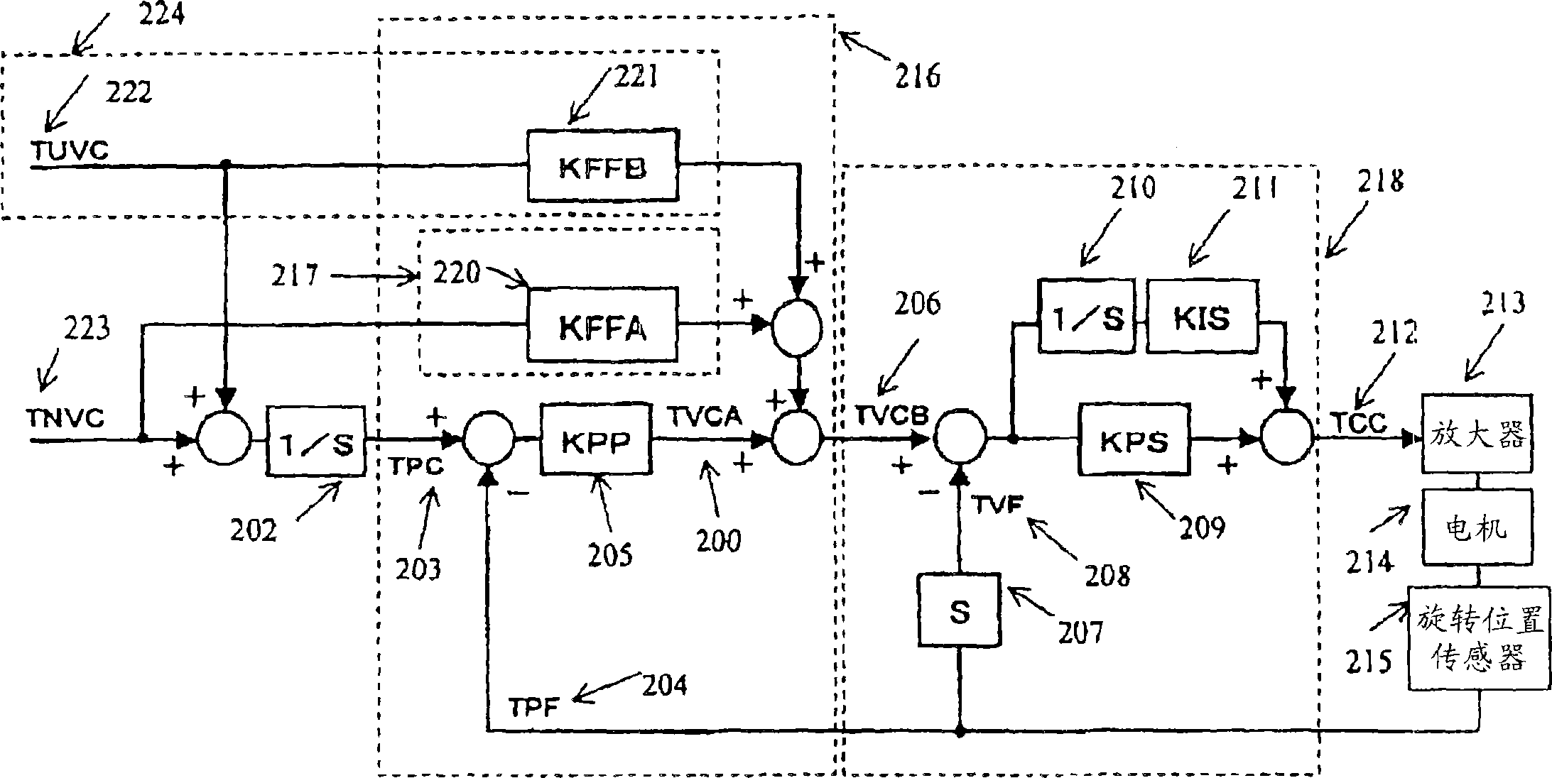
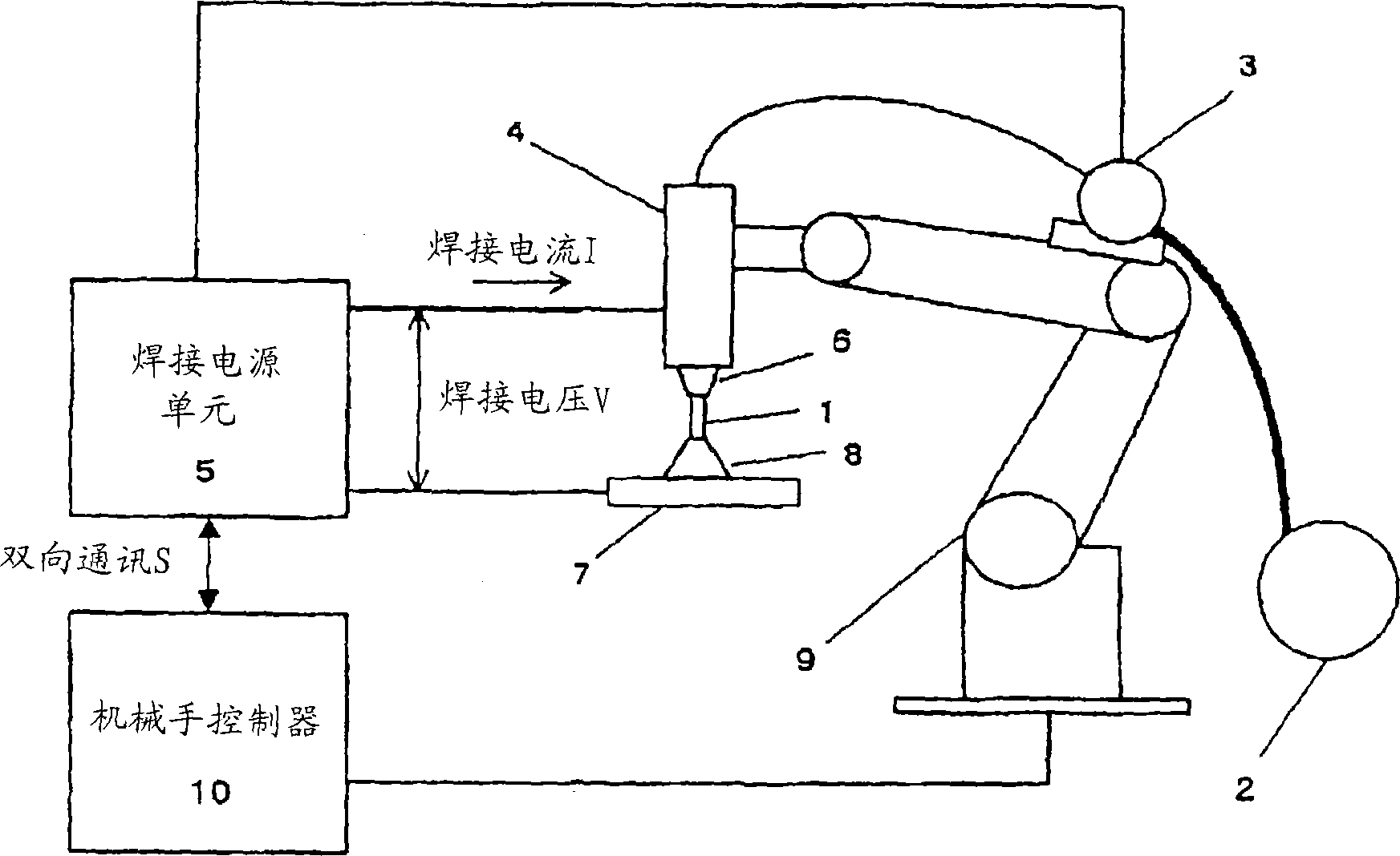
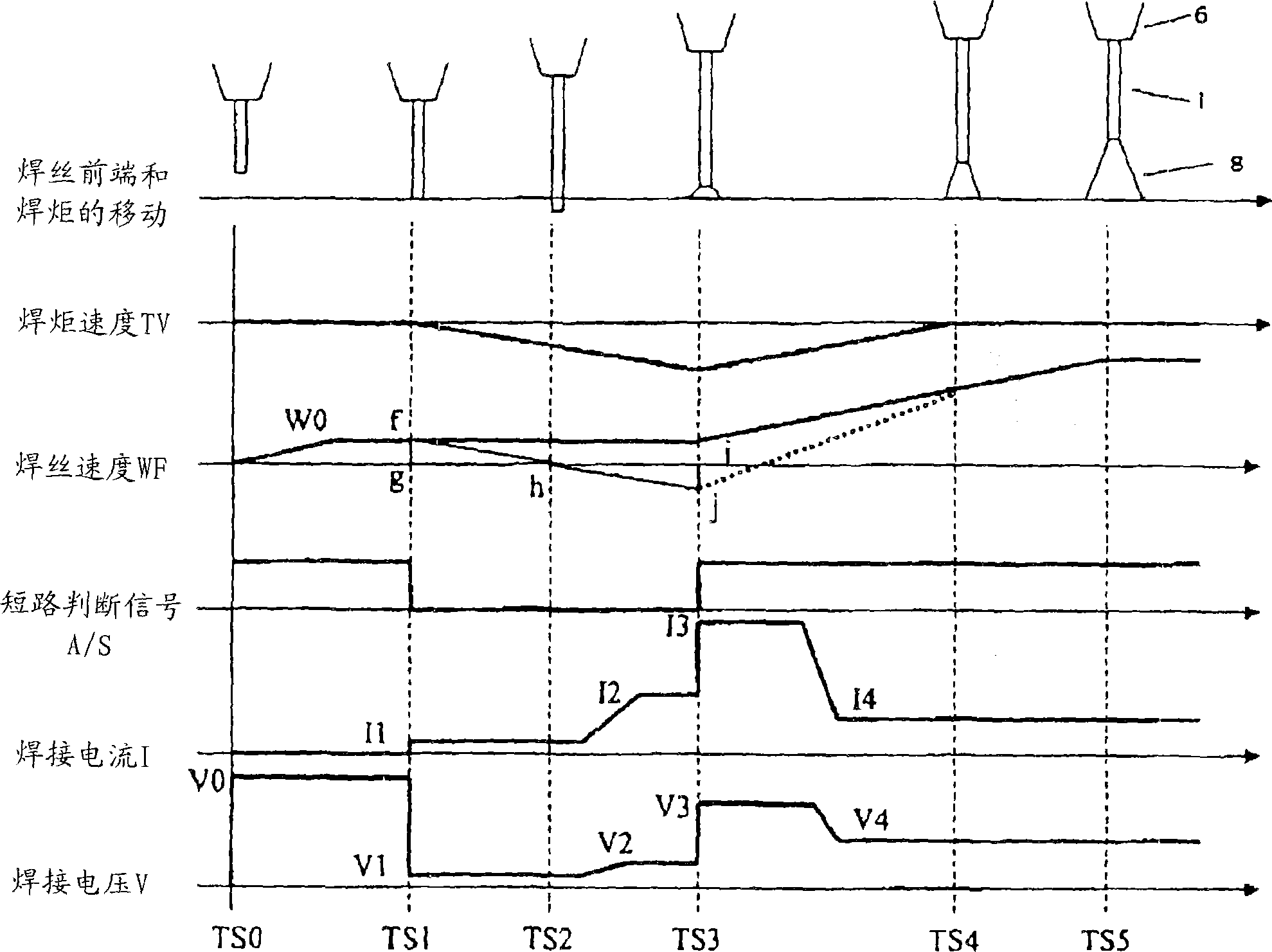
[0114] refer to figure 2 and 3 , the configuration and arc starting process of the welding system in this embodiment will be described. Next refer to figure 1 , 7 and 8, the position control loop of the manipulator controller 10 in this embodiment will be described.

[0115] figure 2 is a schematic configuration diagram showing the welding system in this embodiment. The welding wire 1 serving as a consumable electrode is supplied from a winding reel 2 in the direction of the welding torch 4 by means of a wire feed motor 3 .

[0116] The welding power supply unit 5 applies a preset welding current I and welding voltage V between the welding wire 1 and the base material 7 used as a workpiece through the welding torch 4 and the welding chip 6, thereby generating an arc 8, and controls the welding wire feeding motor 3 to perform welding .

[0117] A ...


PUM


Abstract

Welding system and consumable electrode welding methodA torch is moved by a manipulator in a direction separating from a base material 7 while a wire is supplied, whereby an actuator driving the robot manipulator can control a velocity of the wire for a workpiece by a unidirectional operation of separating the torch, and vibration due to reverse of torch velocity is not generated. Further, by using a dedicated separation control system, velocity follow-up performance of the actuator moving the torch can be heightened without increasing overshoot in the usual operation time, and the acceleration and deceleration time of the manipulator can be reduced.

Description

technical field [0001] The invention relates to a control method for controlling the position of a welding manipulator driven by a motor. Background technique [0002] Recently, in the welding industry, efforts have been made to increase productivity. Specifically, the need to reduce short stoppages of production lines caused by glitches and to shorten production tact times is greater than ever. [0003] A number of factors are believed to be responsible for the stoppage of the production line. The biggest reason is due to poor arc start. [0004] Therefore, in the arc start of the conventional consumable electrode type welding process, when a start signal is input from the outside, the robot manipulator is driven to move the welding torch to a known welding start position. After that, in a state where the wire feed is stopped, the torch is moved by the manipulator in a direction approximate to the feed direction of the wire, and the leading end of the wire is gradually b...

Claims


Application Information

Patent Timeline
IPC IPC(8): B23K9/12B23K9/067
Inventor 中田广之向井康士池田达也增永直人古和将本内保义
Owner PANASONIC CORP
Why Eureka
Try Eureka