
Temperature sensor based on resistance measuring, and radiant heater provided with a temperature sensor of this type

A temperature sensor and resistance measurement technology, applied in the field of radiant heating bodies, can solve the problems of slow response to temperature changes, spending a lot of energy, etc., and achieve the effect of good durability

Inactive Publication Date: 2007-01-31
E G O ELEKTRO GERAETEBAU GMBH
View PDF1 Cites 5 Cited by
  • Summary
  • Abstract
  • Description
  • Claims
  • Application Information

AI Technical Summary

Problems solved by technology

Disadvantages of this rod expansion regulator are: the change of the switching point of the rod expansion regulator requires great effort and the reaction of the rod expansion regulator to temperature changes is slow

Method used


Image

  • Temperature sensor based on resistance measuring, and radiant heater provided with a temperature sensor of this type
  • Temperature sensor based on resistance measuring, and radiant heater provided with a temperature sensor of this type
  • Temperature sensor based on resistance measuring, and radiant heater provided with a temperature sensor of this type

Examples


Embodiment Construction

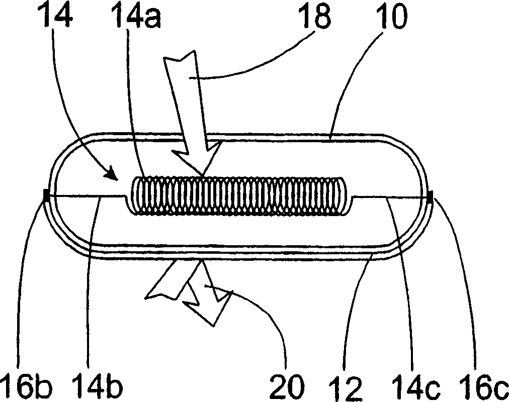
[0033] figure 1A temperature sensor according to the invention is shown which has a tubularly extending housing 10 . Both ends of the case 10 are closed, so the whole is hermetically sealed. One side of the casing has a reflective layer 12 . No heat radiation penetrates into the housing on this side. Inside the housing 10 , a sensor element 14 is arranged parallel to the main extension direction of the housing 10 . The sensor element 14 has a coil 14a and two lead wires 14b, 14c. Leads 14b, 14c are led out of the housing at the ends of the housing and are connected to connection contacts 16b, 16c of the temperature sensor.

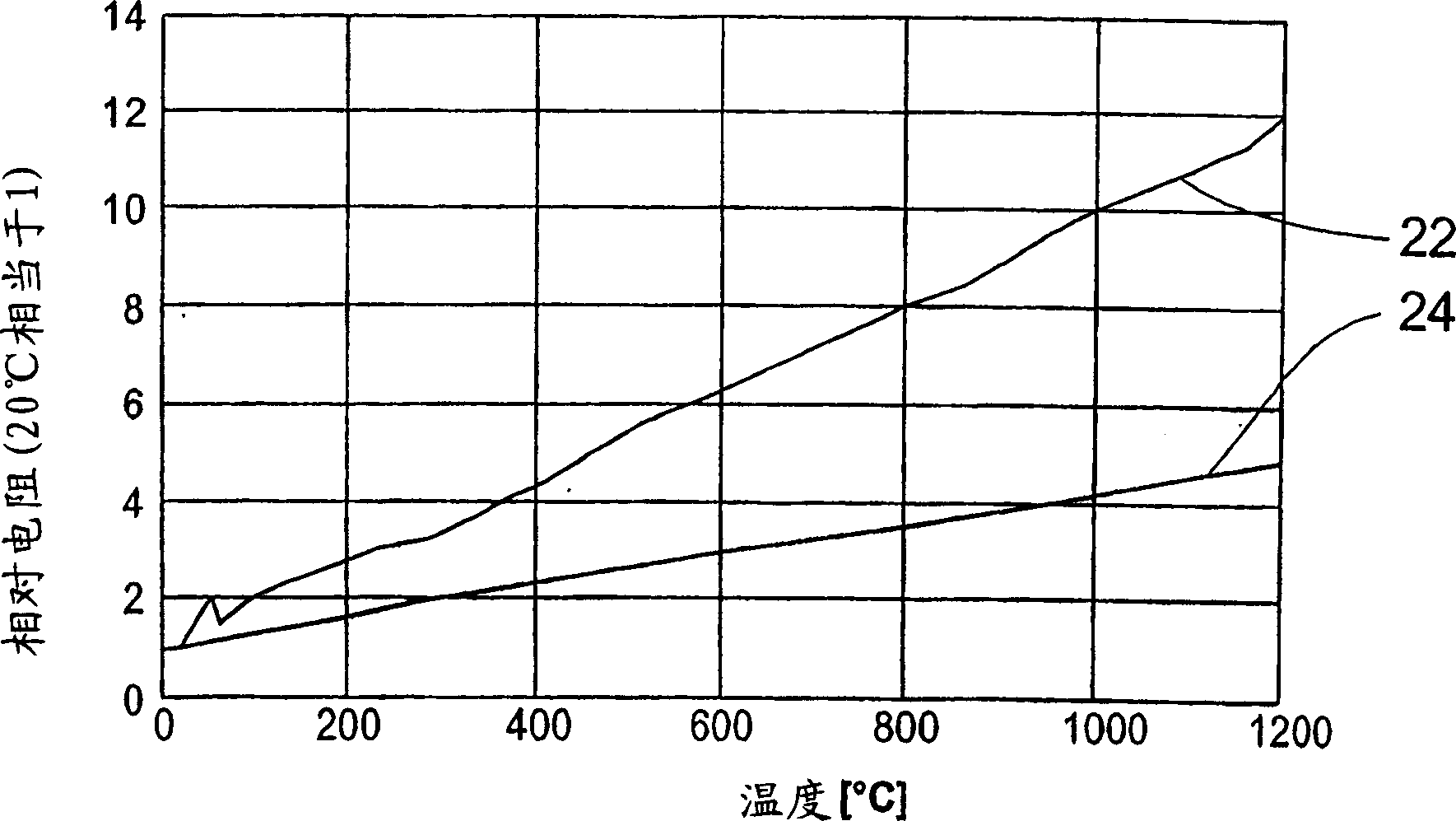
[0034] The heat radiation 18 reaches the housing 10 on the non-reflecting side, enters the housing 10 and heats the sensor element 14 there, in particular the heating coil 14a. Due to the positive temperature coefficient characteristic of the coil 14a, the resistance increases with temperature, and the measurement of the voltage and the current intens...


PUM


Abstract

In one embodiment, a temperature sensor comprises a sensor element (14) having a temperature-dependent resistance and a closed covering (10) or a quartz glass tube for the sensor element. It can advantageously be a common halogen lamp used for spotlights or the like. This depicts a convenient ability to precisely measure temperatures in a radiant heater (26).

Description

technical field [0001] The invention relates to a temperature sensor based on resistance measurement, in particular for a radiant heating body, and to a radiant heating body. Background technique [0002] It is known to equip the cooking zone of the hob with a sensor system which switches off the heating of the hob when the maximum permissible temperature of the hob is reached. Rod expansion regulators are generally used here, which are made of two different materials with different coefficients of thermal expansion. When the designed temperature is reached, the differential expansion caused by the heating causes the two contacts to disconnect from each other, thereby interrupting the power supply to the cooking zone heating. Disadvantages of such rod expansion regulators are that changing the switching point of the rod expansion regulator requires considerable effort and that the rod expansion regulator reacts slowly to temperature changes. Contents of the invention [...

Claims


Application Information

Patent Timeline
Patent Type & Authority Applications(China)
IPC IPC(8): G01K7/18G01K7/16H01C3/00H01C3/14H05B3/74
CPCG01K7/16H05B3/746H05B2203/02G01K7/18H01C3/14
Inventor W·蒂姆W·维滕哈根
Owner E G O ELEKTRO GERAETEBAU GMBH
Learn More