Charge pump power supply

A technology of charge pump and charge, which is applied in static memory, instrument, and conversion equipment without intermediate conversion to AC, etc. It can solve the problems of large circuit scale, potential overlap, large energy loss, etc., and achieve stable flow and reduced size. Effect

Inactive Publication Date: 2007-01-31
CONVERSANT INTPROP MANAGEMENT INC
View PDF0 Cites 15 Cited by
  • Summary
  • Abstract
  • Description
  • Claims
  • Application Information

AI Technical Summary

Problems solved by technology

The four-stage, four-phase charge pump also results in a larger circuit size and greater energy loss at the higher peak and average current levels requir

Method used


Image

  • Charge pump power supply
  • Charge pump power supply
  • Charge pump power supply

Examples


Embodiment Construction

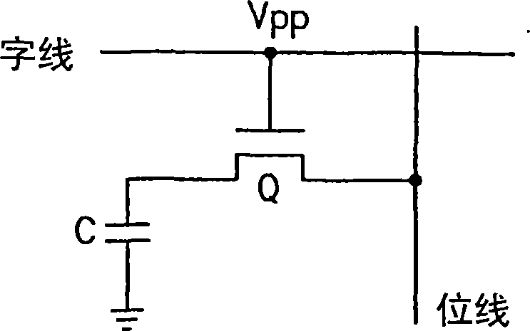
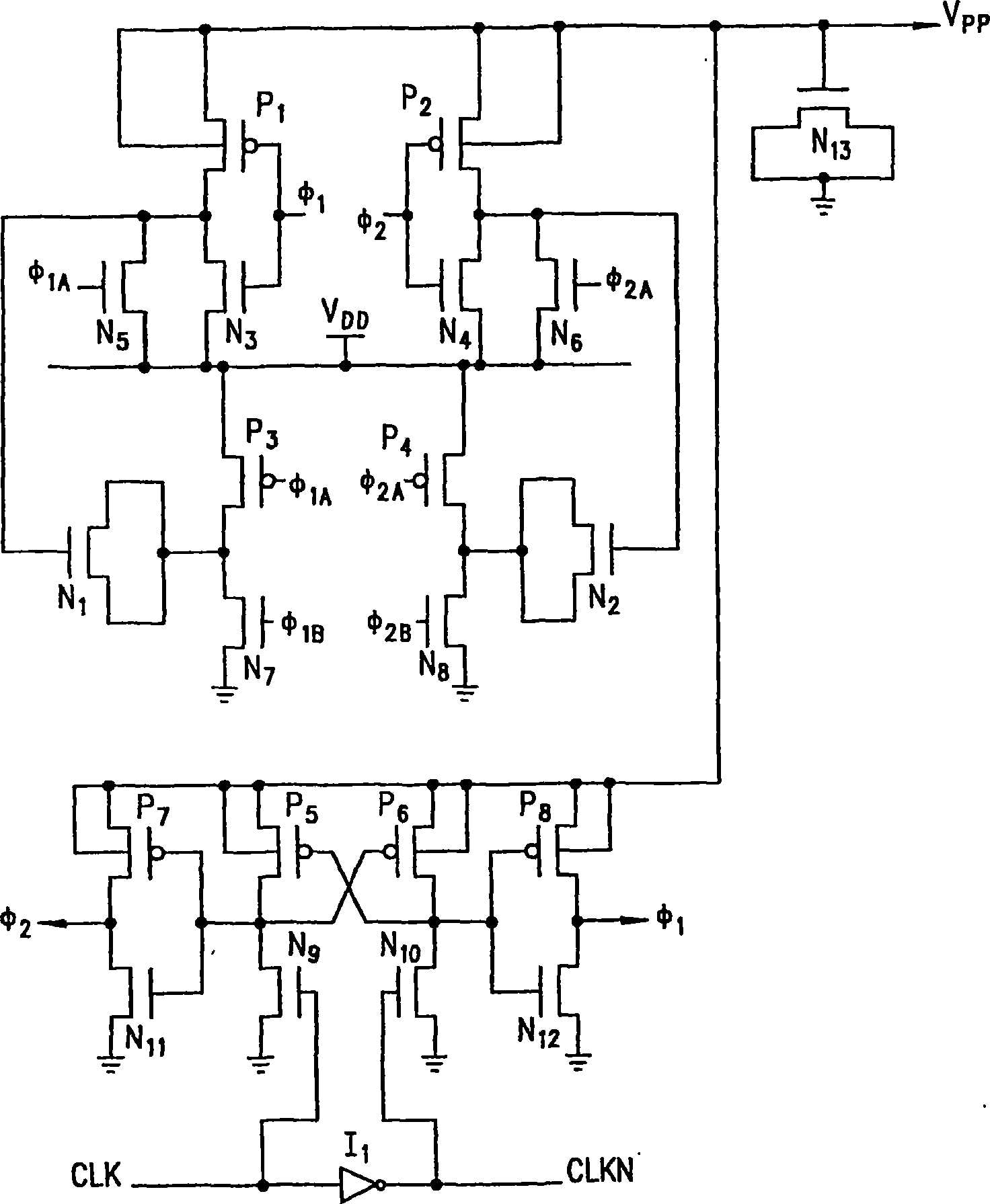
[0031] Figure 5A is a schematic diagram of a charge pump circuit 200 according to one embodiment of the present invention. Charge pump circuit 200 includes two pump cascades 300 and 400 connected in parallel to output node 210 . Each pump cascade includes three pump stages connected in series between the input supply voltage Vdd and the output node 210 . It should be pointed out that although Figure 5A Only three pump stages are shown, but a greater number of pump stages may be used in other embodiments.

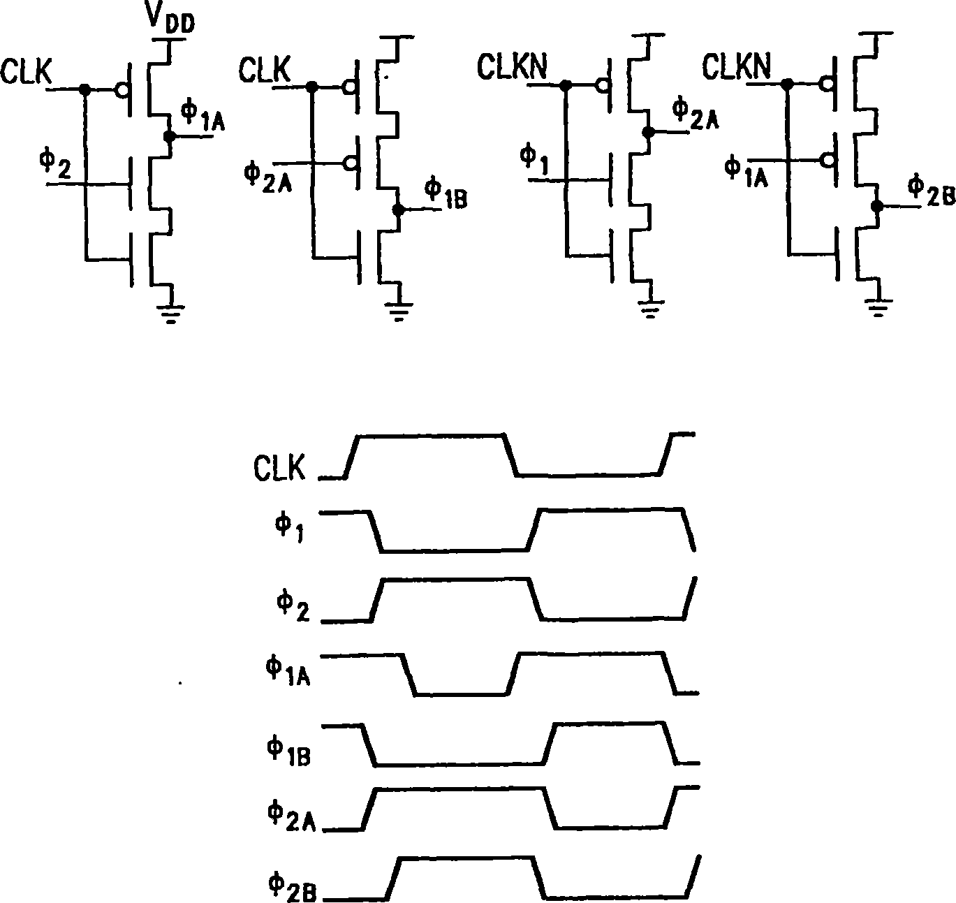
[0032] The input supply voltage Vdd and the driving clock signals PHI1 and PHI2 are input to the pump stages 300 and 400 . The input power supply voltage Vdd provides the charge source for the charge pump. Such as Figure 5B As shown, the non-overlapping drive clock signals PHI1 and PHI2 are driven by opposite phases of the input clock signal CLK.

[0033] The respective pump stage of each pump cascade of charge pump circuit 200 is clocked in the opposite phase of th...


PUM


Abstract

The present invention discloses a charge pump based power supply for low voltage dynamic random access memory (DRAM), including a charge pump and a non-overlapping clock signal generator. The charge pump consists of a cascade of two pumps coupled in parallel. Each pump cascade consists of multiple pump stages connected in series between the supply voltage and the output node. Each cascaded adjacent stage is clocked at the opposite phase of the system clock signal. The charge pump drives the output node on the rising and falling edges of the system clock signal. The non-overlapping clock signal generator includes charge-sharing transistors controlled by equalization pulses generated by the outputs of latches that equalize the non-overlapping output clock signals by charge sharing during non-overlapping periods between system clock phases. The non-overlapping clock signal generator also includes transmission gates that ensure equalization of the non-overlapping cycles.

Description

[0001] This application claims priority to US Provisional Patent Application SC / Serial No. 60 / 252,219, filed November 21, 2000, and entitled "Charge Pump Based on Low Voltage DRAM Power Supplies." technical field [0002] The present invention relates to charge pumps for boosting supply voltages to obtain high voltages. In particular, the present invention relates to charge pumps based on power supplies for use with low voltage dynamic random access memory (DRAM). Background technique [0003] Voltage multipliers are commonly used to step up the voltage of a power supply to provide the high voltage required to operate circuit components. One type of voltage multiplier is called a charge pump and is commonly used in memory systems to provide the voltages needed to access, program or erase memory cells. [0004] For example, in the field of dynamic random access memory (DRAM), charge pump circuits are commonly used to generate the voltages that enable memory cells to access t...

Claims


Application Information

Patent Timeline
IPC IPC(8): H02M3/07G11C5/14H03K5/151
Inventor 保罗·W·迪莫内
Owner CONVERSANT INTPROP MANAGEMENT INC
Why Eureka
Try Eureka