Micro bubble generation device

A micro-bubble generation and air chamber technology, applied in the field of water treatment, can solve the problems of poor quality, low efficiency, and small number of micro-bubbles, and achieve the effects of reducing energy consumption, simple mechanical structure and saving investment.

Inactive Publication Date: 2007-02-07
陈翼孙 +1
View PDF0 Cites 27 Cited by
  • Summary
  • Abstract
  • Description
  • Claims
  • Application Information

AI Technical Summary

Problems solved by technology

[0015] The purpose of the present invention is to provide an improved microporous bubble generating device, which can overcom

Method used


Image

  • Micro bubble generation device
  • Micro bubble generation device
  • Micro bubble generation device

Examples


Embodiment 1

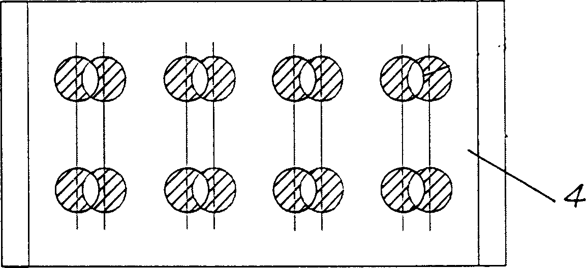
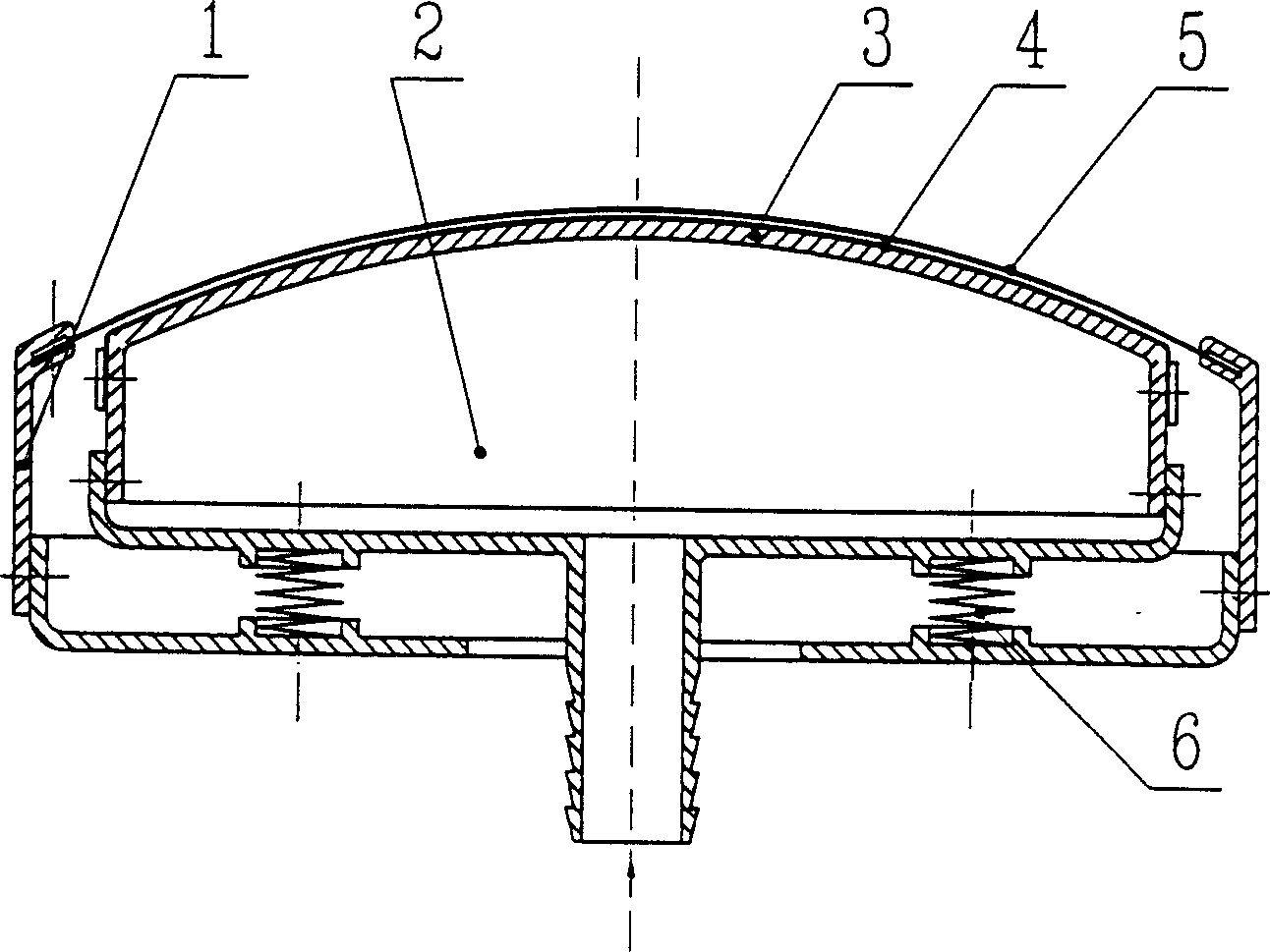
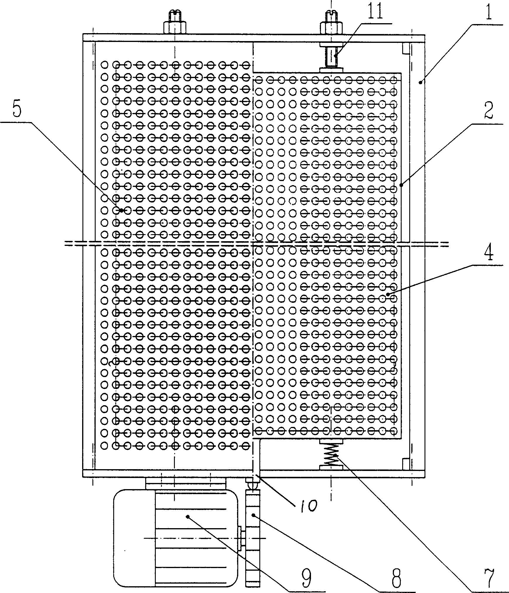
[0027] The air enters the air distribution chamber 2 through the air inlet, and then distributes air through the small holes of the fixed perforated plate 4; outside the fixed shell, the fixed perforated plate 4 is pushed against the moving perforated plate 5 by the lifting spring 6, so that the two The curved surfaces of the thin plates coincide, and at the same time, under the action of the motor 9 and the cam 8, the mobile skeleton drives the mobile perforated plate to make a small horizontal displacement, and the displacement distance is 1 / 2 the hole pitch. The power of its displacement comes from motor 9. The motor drives the waveform cam 8 to rotate, and through the ups and downs of the waveform cam, the cam ejector rod 10 close to it is reciprocated, which continuously causes the adjustment spring 7 to vibrate back and forth, and drives the mobile perforated plate 5 to reciprocate. The small holes on the two-layer orifice plate are therefore continuously penetrated or c...

Embodiment 2

[0029] The air enters the air distribution chamber 2 through the air inlet, and then distributes air through the small holes of the fixed perforated plate 4; outside the fixed shell, the fixed perforated plate 4 is pushed against the moving perforated plate 5 by the lifting spring 6, so that the two At the same time, under the action of the motor 9 and the cam 8, the rotating frame 12 connected with the cam rotates around the central axis 13, and the moving perforated plate 5 also rotates at this time, so that the two-layer orifice plate Therefore, the small holes on the plate are continuously penetrated or closed, even if the continuous air flow is cut, the small air bubbles can quickly leave the plate and float up. The fixed perforated plate and the movable perforated plate are all stainless steel thin plates, and the plates are densely covered with small holes with a diameter of 0.5mm. This thin metal orifice plate is easy to clean. Not only does it reduce the possibility ...


PUM

PropertyMeasurementUnit
Apertureaaaaaaaaaa

Abstract

The invention relates to a micro foam generator, which is characterized in that: the cam is connected to a movable skeleton; the movable skeleton has gas distribute room; the top of gas distribute room and the top of movable skeleton both have one porous plate; the gas distribute room is connected to the movable skeleton via lifting spring; when using, the air enters into gas inlet to enter gas distribute room; said two porous plates are layered, while one is frequently moved, to switch the micro hole, and high-speed shear the airflow, to make the foam small and quickly leave the surface of porous plate, and the size of micro foam can be controlled, to increase the effective foam number. The invention has simple structure and lower cost.

Description

Technical field: [0001] The invention relates to the technical field of water treatment, in particular to a generating device capable of producing microbubbles. Background technique: [0002] The most commonly used methods are as follows: [0003] 1. Decompression and release method [0004] It is under the condition of pressurization, so that the gas is forcibly dissolved into the water, and then suddenly decompressed to make it precipitate from the crystal lattice of water molecules, forming countless microbubbles. Obviously, in order to obtain microbubbles, a process of pressurization and decompression is required, which consumes a lot of energy and is not desirable. However, because the air bubbles released by this method are stable and uniform, they are still mostly used in air flotation water purification. [0005] 2. Suction cutting method: [0006] It uses the negative pressure generated by the rotation of the impeller or the water jet to inhale the air, cut it, ...

Claims


Application Information

Patent Timeline
IPC IPC(8): B01F3/04C02F7/00
CPCY02W10/10
Inventor 陈翼孙黄永宽
Owner 陈翼孙
Why Eureka
Try Eureka