Manufacture method and die for powder metallurgy inside spin ratchet wheel

A powder metallurgy and mold manufacturing technology, which is applied to the manufacturing method of powder metallurgy inner helical ratchet and the field of molds, can solve the problems of inability to form special-shaped internal helical gears, difficult control of the rotation speed of rotating parts, damage to molds and ingredients, etc. The effect of lowering, easier speed control, lower production cost

Inactive Publication Date: 2007-02-07
南通市海门常乐粉末冶金厂
View PDF0 Cites 32 Cited by
  • Summary
  • Abstract
  • Description
  • Claims
  • Application Information

AI Technical Summary

Problems solved by technology

However, during the pressing process, the upper and lower die punches must rotate with the pressing, so it is impossible to form special-shaped internal helical gears with non-circular outer diameters
In addition, during the pressing process, the rotation speed of the rotating parts is not easy to control, so it is easy to cause damage to the mold and ingredients, and the yield is low

Method used


Image

  • Manufacture method and die for powder metallurgy inside spin ratchet wheel
  • Manufacture method and die for powder metallurgy inside spin ratchet wheel

Examples


Embodiment 1

[0063] A method for manufacturing a powder metallurgy internal helical ratchet, the method comprising the following steps:

[0064] The first step, mixing ingredients: mix the following powders evenly, in terms of mass percentage, wherein copper accounts for 1.5-2%, nickel accounts for 1.7-2%, molybdenum accounts for 0.5%, carbon accounts for 0.5%, manganese sulfide accounts for 0.3%, Micro-wax powder accounts for 0.3%, and the rest is the powder of pre-alloyed iron powder, mixed evenly,

[0065] The second step, pressing and forming: put the above powder in a pressing mold with a small mandrel rotation system with a friction plate structure and press it into a green compact with an inner spiral ratchet shape, with a pressure of 1100±5KN, pressing Density ≥ 6.85g / cm 3 , such as pressing density can be 7.2g / cm 3 , 7.3g / cm 3 ,

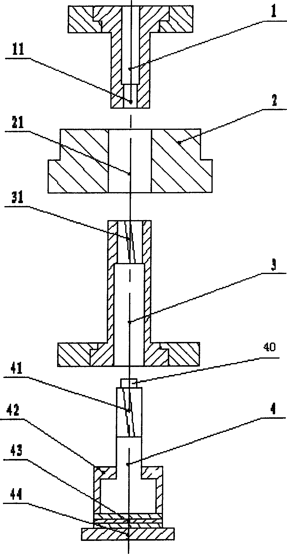
[0066] Wherein, it is composed of a pressing upper punch 1, a pressing middle die 2, a pressing lower punch 3, and a pressing mandrel member 4. The ...

Embodiment 2

[0071] A manufacturing mold for a powder metallurgy internal spiral ratchet, which consists of a pressing upper punch 1, a pressing middle die 2, a pressing lower punch 3, and a pressing mandrel member 4. The raw material powder is placed in the pressing middle die 2 and placed in the pressing lower punch 3 and the pressing upper punch 1, the lower part of the pressing upper punch 1 is provided with a limit hole 11 that matches the limit block 41 on the upper end of the mandrel 4. The shape of the limit block 41 is usually cylindrical. Cooperate, the shape of the limit hole 11 is also cylindrical, the shape of the inner mold cavity 21 of the pressing middle mold 2 is the same as the outer profile of the inner spiral ratchet wheel, and the upper part of the pressing lower punch 3 is provided with an outer spiral of the pressing mandrel member 4. The inner helical tooth 31 that tooth 41 matches, wherein the axial length of outer helical tooth 41 is longer than inner helical tooth...


PUM

PropertyMeasurementUnit
densityaaaaaaaaaa
diameteraaaaaaaaaa
surface areaaaaaaaaaaa

Abstract

The invention relates to a method for producing powder smelt screw ratchet, which comprises: mixing the materials, compressing molding, sintering, compressing and shaping, to obtain the ratchet. The invention also discloses a relative mould, which is formed by a compressing upper punch, compressing middle mould, compressing lower punch; the upper part of lower punch has the inner screw tooth matched with the outer screw tooth; the upper punch is sliding matched with the middle mould; the middle mould is sliding matched with the lower mould; the compressing core rod has compressing core rod, friction plate, and rotation element; the upper part of compressing core rod has outer screw tooth; the lower end of core rod and the upper end of rotating element have friction plate between them, while their contact surface has lubricant. The invention, via the rotation of core rod, realizes the one-time molding and demoulding of inner screw ratchet, to improve the yield and reduce the cost.

Description

technical field [0001] The invention relates to a forming method and a mold of an internal spiral ratchet, in particular to a manufacturing method and a mold of a powder metallurgy internal spiral ratchet. Background technique [0002] The mechanical properties and precision of powder metallurgy parts firstly depend on the density and its uniformity, and are closely related to the raw materials used, pressing, sintering, processing techniques, molds, equipment, etc. The general helical gear forming technology uses flat ball bearings to be placed between the upper and lower die punches and the pads connected to the machine for rotary pressing, and on this basis, the internal helical tooth pressing technology has been developed. However, during the pressing process, the upper and lower die punches must rotate with the pressing, so it is impossible to form a special-shaped internal helical gear with a non-circular outer diameter. In addition, during...

Claims


Application Information

Patent Timeline
Patent Type & Authority Applications(China)
IPC IPC(8): B22F3/16
Inventor 宋永盛高瑞华汤春华宋永刚
Owner 南通市海门常乐粉末冶金厂
Why Eureka
Try Eureka