
Corrugated-type board automatic welding machine

A technology of automatic welding machine and corrugated plate, applied in the direction of welding rod characteristics, welding equipment, arc welding equipment, etc., can solve the problems of uneven penetration of weld bead, easy deviation of weld bead, high welding requirements, etc.

Inactive Publication Date: 2007-02-07
成都鑫兴众力科技发展有限公司
View PDF0 Cites 17 Cited by
  • Summary
  • Abstract
  • Description
  • Claims
  • Application Information

AI Technical Summary

Problems solved by technology

[0002] At present, there are a lot of automatic welding equipment, but the welding equipment for container corrugated boards is not ideal, because the cross-section of container corrugated boards is in the shape of a "bow", which has a special shape. The inflection point at the corner is generally arc-shaped, and the steel plate It is not thick. During the working process, the welding requirements are particularly high. The existing welding equipment cannot meet the special requirements of container corrugated welding. Due to the difficulty of the welding process itself and the limitation of the equipment's own functions, the welding torch for the corrugated section is not ideal. Welding status, such as the welding robot workstation can not solve the problem of welding torch tracking well, and other special equipment can not solve the problem of welding torch swing angle. At the same time, there is no real-time tracking during the welding process, resulting in different dry elongation of the welding torch, resulting in uneven penetration of the weld bead Even, the weld bead is easy to deviate, the thickness of the weld is uneven, the welding effect is not good, and the welding cannot be completed automatically; or the welding quality is relatively poor, the degree of automation is low, human assistance is required, and the productivity is low

Method used


Image

  • Corrugated-type board automatic welding machine
  • Corrugated-type board automatic welding machine
  • Corrugated-type board automatic welding machine

Examples


Embodiment Construction

[0034] The corrugated plate automatic welding machine provided by the present invention will be described in detail below in conjunction with the accompanying drawings.

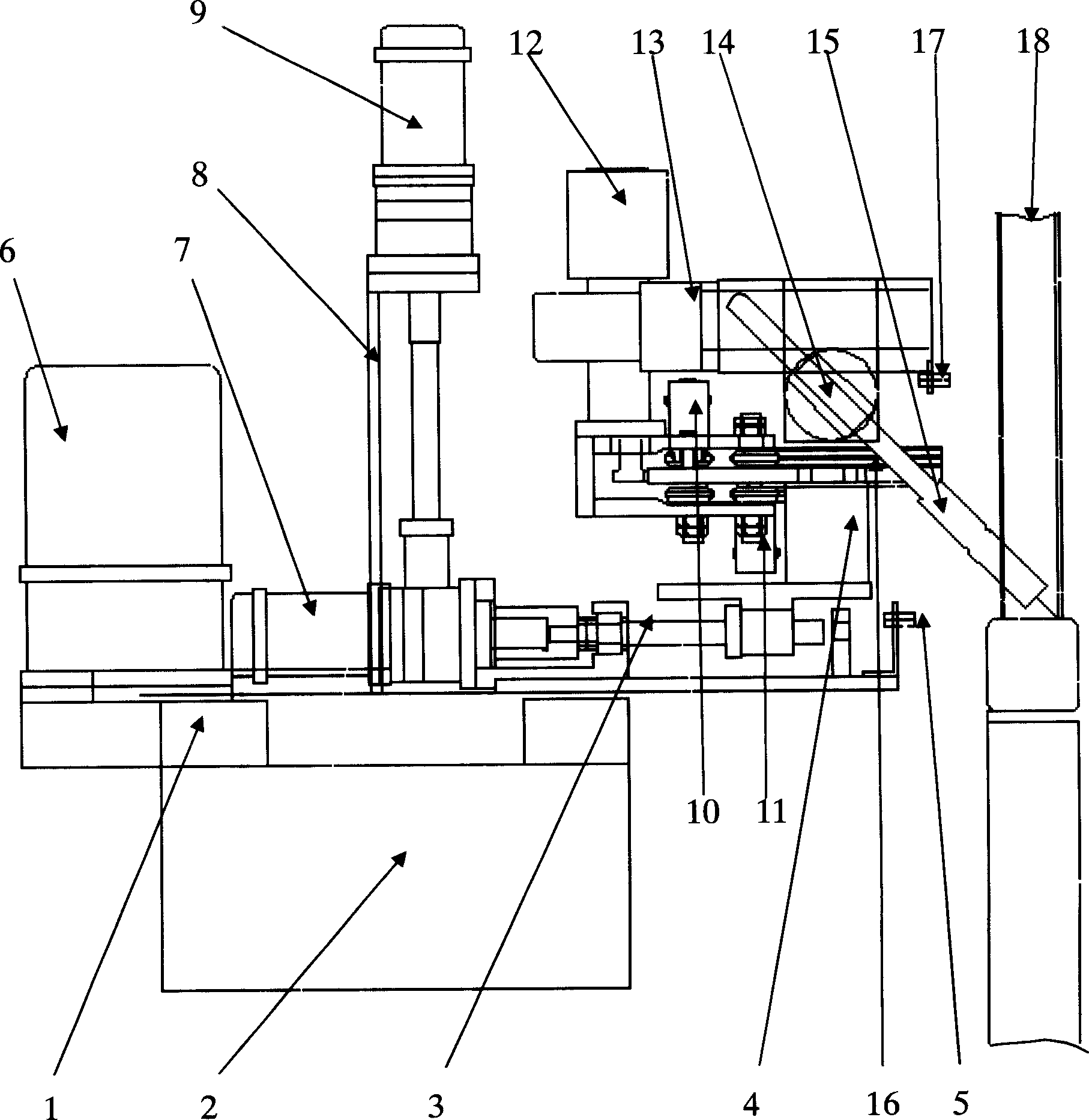
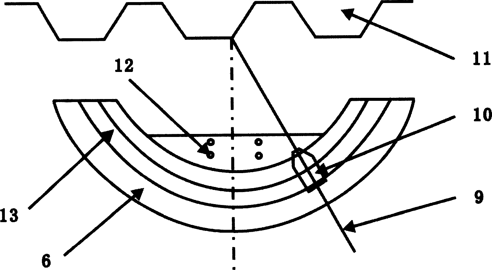
[0035] figure 1 It is the structural representation of the corrugated plate automatic welding machine provided by the present invention, image 3 It is a structural schematic diagram of the welding torch swing angle mechanism of the corrugated plate automatic welding machine provided by the present invention, wherein 1, long axis, 2, movable trolley, 3, short axis, 4, base (support), 5, vertical tracking probe , 6. Long-axis drive motor, 7. Short-axis drive motor, 8. Fixed backplane, 9. Vertical tracking motor, 10. Balance wheel device, 11. Guide wheel device, 12. Rotary motor, 13. Horizontal row surface tracking Motor, 14, welding torch holder, 15, welding torch, 16, arc-shaped rotary disk, 17, horizontal tracking probe, 18, workpiece, 19, circular arc-shaped track, 20, fixing hole, this corrugated plate au...


PUM


Abstract

The invention relates to a corrugated sheet automatic welding machine, wherein it comprises a frame and a movable cart at the bottom of frame; the frame has a walking system with long axle and short axle while the long axle drives motor and the short axle executes motor; the long axle and the long axle drive motor are connected by gear and tooth bar; the rotation axle of short axle drive motor is connected to the short axle via gear; the welding seam track system comprises a horizontal track executor, a vertical track executor; the welding gun swinger comprises a base, an arc rotation disc, a welding gun clamper, a welding gun clamper fixer and a motor driver; the control system comprises a main control tank, a control panel, an input module, a micro processing module, a storage module, a power module, a welding swinger executing module, a walking system executing module, and a welding seam track module. Said welding machine can weld when the welding gun is always at best position, to realize automatic welding, with uniform welding seam.

Description

technical field [0001] The invention relates to the technical field of welding machines, in particular to an automatic container corrugated welding machine. technical background [0002] At present, there are a lot of automatic welding equipment, but the welding equipment for container corrugated boards is not ideal, because the cross-section of container corrugated boards is in the shape of a "bow", which has a special shape. The inflection point at the corner is generally arc-shaped, and the steel plate It is not thick. During the working process, the welding requirements are particularly high. The existing welding equipment cannot meet the special requirements of container corrugated welding. Due to the difficulty of the welding process itself and the limitation of the equipment's own functions, the welding torch for the corrugated section is not ideal. Welding status, such as the welding robot workstation can not solve the problem of welding torch tracking well, and othe...

Claims


Application Information

Patent Timeline
IPC IPC(8): B23K9/12B23K9/127B23K9/10B23K9/28
Inventor 刘继福杨永家
Owner 成都鑫兴众力科技发展有限公司
Learn More