Over-magnetostriction rod drive membrane pump

A giant magnetostrictive rod and membrane technology, applied to pumps with flexible working elements, pumps, machines/engines, etc., can solve the problem of low power, etc., and achieve the effect of strong self-priming ability, no impact, and low noise

Inactive Publication Date: 2007-02-07
卢全国
View PDF0 Cites 13 Cited by
  • Summary
  • Abstract
  • Description
  • Claims
  • Application Information

AI Technical Summary

Problems solved by technology

[0014] In order to overcome the problem of low power of the existing membrane micropump, the present invention provides a membrane micropump using rod-shaped giant magnetostrictive material as the driving source, which can effectively improve the output power of the micropump

Method used


Image

  • Over-magnetostriction rod drive membrane pump
  • Over-magnetostriction rod drive membrane pump
  • Over-magnetostriction rod drive membrane pump

Examples


Embodiment Construction

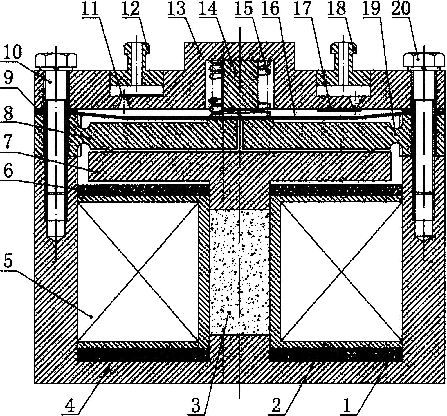
[0029] Such as figure 2 As shown, the present invention includes a lower permanent magnet 1, a bobbin 2, a giant magnetostrictive rod 3, a pump body 4, a drive coil 5, an upper permanent magnet 6, a top plate 7, a left displacement amplification mechanism 8, a sealing ring 9, a left Screw 10, outlet valve 11, outlet pipe 12, pump cover 13, cylinder block 14, spring 15, elastic diaphragm 16, inlet valve 17, water inlet pipe 18, right displacement amplification mechanism 19, right screw 20.

[0030] A circular elastic diaphragm 16 and an annular sealing ring 9 are installed between the barrel-shaped pump body 4 and the pump cover 13. The elastic diaphragm 16 divides the inner cavity of the pump body 4 into upper and lower parts. The cavity between the elastic diaphragm 16 and the pump cover 13 is the pump working chamber. Inside the cavity between the elastic diaphragm 16 and the pump body 4, a left displacement amplification mechanism 8 and a right displacement amplification ...


PUM


Abstract

The invention relates to a film micro pump driven by ultra magnetic deformation rod, wherein one flexible film (16) is mounted between the pump (4) and the pump cover (13); the flexible film (16) and the pump cover (13) form sealing working chamber; inside the chamber, the left-displacement amplifier (8), the right-displacement amplifier (19), the top disc (7), the upper permanent magnet (6), the coil skeleton (2) coiled with driving winding (5), and the lower permanent magnet (1) are arranged from up to down; the through hole at the middle of skeleton (2) is mounted with ultra magnetic deformation rod; the spring (15) is mounted between the pump cover (13) and flexible film (16) to form pre-compressor with the pump cover (13); the pump cover (13) is mounted with water inlet tube (18) and water outlet tube (12), to connect the working chamber and outer space via inlet valve (17) and outlet valve (11). The invention can be used in the condition that demands high power and low-voltage driving.

Description

Technical field [0001] The invention relates to a membrane micropump using a giant magnetostrictive material as a driving source. Background technique [0002] In a microfluidic system, a micropump as an actuator is one of the most important devices. Structurally, existing micropumps include mechanical micropumps and non-mechanical micropumps. Mechanical micropumps transfer control fluid through moving parts. Non-mechanical micropumps do not have any moving parts, and are generally driven by electro-hydraulic force, ultrasonic waves, electroosmosis, continuous electrowetting, magneto-hydraulic force, and air bubbles. [0003] The mechanical micropumps widely studied and used at present are mainly membrane micropumps. The membrane micropump is a positive displacement pump, relying on the bending deformation of the vibrating membrane to change the volume of the pump chamber, which in turn causes the change of the pressure of the pump chamber, so as to complete the direction...

Claims


Application Information

Patent Timeline
Patent Type & Authority Applications(China)
IPC IPC(8): F04B43/02
Inventor 卢全国李立方陈定方李勋祥刘德辉魏国前唐刚欧阳琳
Owner 卢全国
Why Eureka
Try Eureka