Eureka AIR delivers breakthrough ideas for toughest innovation challenges, trusted by R&D personnel around the world.

Laser reparation method for organic el element and laser reparation device

A repair method and component technology, applied in the direction of organic semiconductor devices, electrical components, measuring devices, etc., can solve problems such as pixel loss of function

Inactive Publication Date: 2007-02-07
ITES
View PDF0 Cites 4 Cited by
  • Summary
  • Abstract
  • Description
  • Claims
  • Application Information

AI Technical Summary

Problems solved by technology

Because the current laser repair method and device do not have the method and means to accurately and locally grasp the defect area, the repair using the current laser repair method and device often makes the entire pixel with the defect lose its function

Method used


Image

  • Laser reparation method for organic el element and laser reparation device
  • Laser reparation method for organic el element and laser reparation device
  • Laser reparation method for organic el element and laser reparation device

Examples


Embodiment approach 1

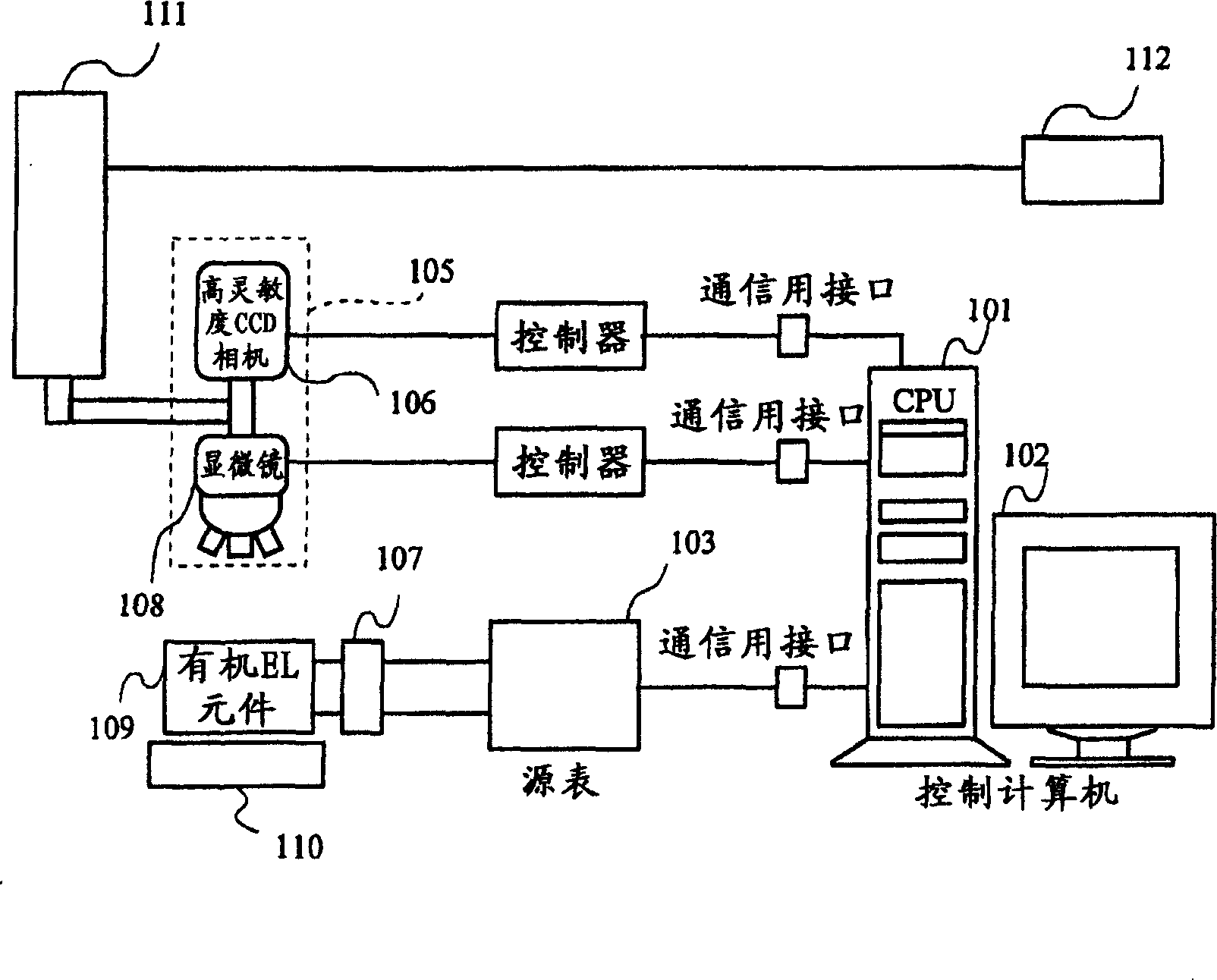
[0048] figure 1 It is a block diagram showing the configuration of the inspection device according to Embodiment 1 of the present invention.

[0049] The inspection device according to Embodiment 1 of the present invention includes a control computer 101 , a display device 102 , a holder 110 , a probe 107 , a source meter 103 , a camera 105 , a laser irradiator 111 , and a laser adjuster 112 . The control computer 101 controls the display device 102 , the holder 110 , the probe 107 , the source meter 103 , and the camera 105 . The organic EL element 109 to be repaired is placed on the holder 110 and electrically connected to the source meter 103 through the probe 107 . The source meter 103 is controlled by the control computer 101 and applies a commanded voltage to the organic EL element 109 through the probe 107 . Also, the source meter 103 is controlled by the control computer 101 , measures the voltage and current characteristics of the organic EL element 109 , and sends ...

Embodiment approach 2

[0056] The restoration method according to Embodiment 2 of the present invention will be described below.

[0057] Figure 4 It is a flowchart showing the restoration method according to Embodiment 2 of the present invention. Refer to below Figure 4 and figure 1 side to explain. First, the organic EL element to be repaired is set on the holder 110, the voltage-current characteristic of the organic EL element 109 is obtained by the source meter 103, and the voltage-current characteristic is compared with a reference voltage determined based on the voltage-current characteristic of a normal organic EL element. The current characteristics are compared to determine whether or not a so-called leakage current flows in the organic EL element to be repaired, and obtain a leakage current value (S401). When there is a leakage current here, it can be considered that there is a high possibility that some kind of defective region exists in the organic EL element to be repaired.

[00...


PUM


Abstract

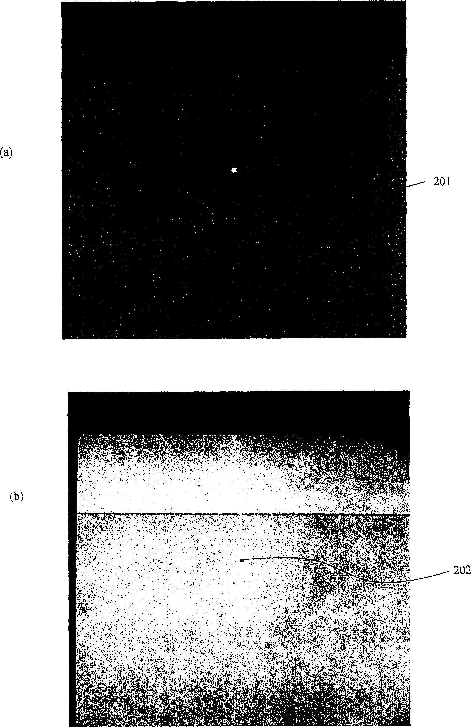
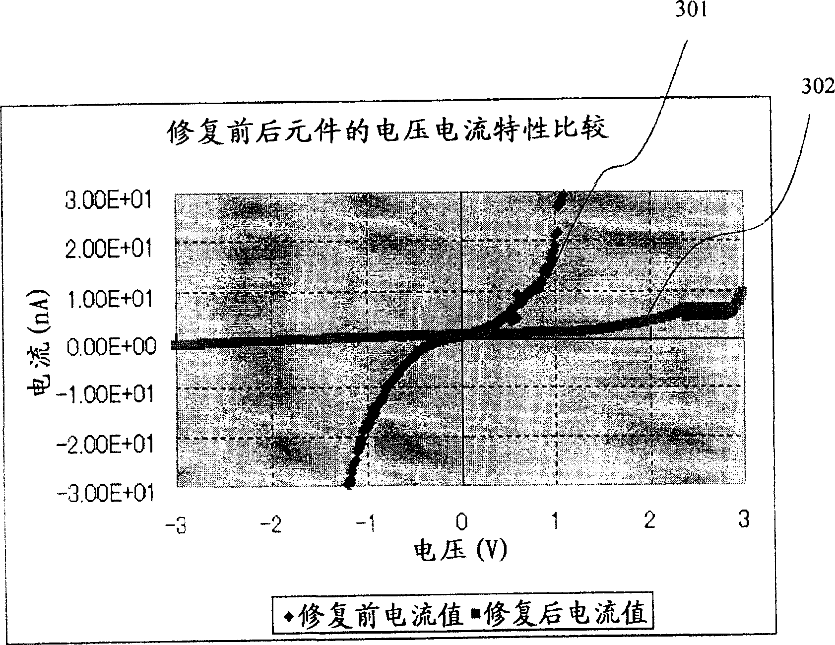
The invention provides a repairing method of an organic EL by laser, in which a position of a defective part of an organic EL element is precisely grasped and laser is irradiated to the specific area and such defective parts only are repaired, without impairing a function of the whole of the organic EL elements in the pixel having a defective part and maintaining a luminous function of other organic EL elements than defective ones. A current voltage characteristic of an organic EL element is measured and an existence of a leak current is judged by comparing such current voltage characteristics with a predetermined current voltage characteristics. A leak luminous image is obtained by impressing a voltage less than a luminescence threshold on the organic EL element, and laser is irradiated and the leak luminous part is repaired. Repairing is confirmed when there is no leak luminous image by impressing a voltage less than a luminescence threshold on the organic EL element and a leak current is decreased when a current voltage characteristic is measured.

Description

technical field [0001] The invention relates to a repairing method and a repairing device for repairing a defect area of ​​an organic EL element by using a laser. Background technique [0002] In recent years, an organic EL display device using an organic EL (Electro Luminescence) element as a display device has attracted attention. The organic EL element is a self-luminous element, which has the advantages of wide viewing angle, no backlight, low power consumption, and fast response speed. [0003] The organic EL element has the following structure: an organic EL layer with a light-emitting function is sandwiched between the anode and the cathode, and the organic EL layer is formed by laminating a hole transfer layer, a light-emitting layer, and an electron transfer layer. [0004] An organic EL display device can be configured by arranging the organic EL elements in a matrix on a substrate. [0005] Most of the defects of the organic EL element are caused by contaminatio...

Claims


Application Information

Patent Timeline
Patent Type & Authority Applications(China)
IPC IPC(8): H05B33/10G01R31/00G01N21/88
CPCH01L2251/568H10K71/861
Inventor 赤津光俊三浦伸仁筒井长德
Owner ITES
Why Eureka
Eureka Blog
Learn More