Hydraulic or pneumatic shaping method and device of plate material

A hydraulic and pneumatic technology, applied in the field of sheet hydraulic or pneumatic forming methods and devices, can solve problems such as re-processing molds, and achieve the effects of improving adaptability, simple manufacturing process, and speeding up update speed.

Inactive Publication Date: 2007-02-14
INST OF METAL RESEARCH - CHINESE ACAD OF SCI
View PDF0 Cites 23 Cited by
  • Summary
  • Abstract
  • Description
  • Claims
  • Application Information

AI Technical Summary

Problems solved by technology

[0003] The purpose of the present invention is to provide a hydraulic or pneumatic forming method and device for sheet metal, which solves the problem that the same set of hyd

Method used


Image

  • Hydraulic or pneumatic shaping method and device of plate material
  • Hydraulic or pneumatic shaping method and device of plate material
  • Hydraulic or pneumatic shaping method and device of plate material

Examples


Embodiment Construction

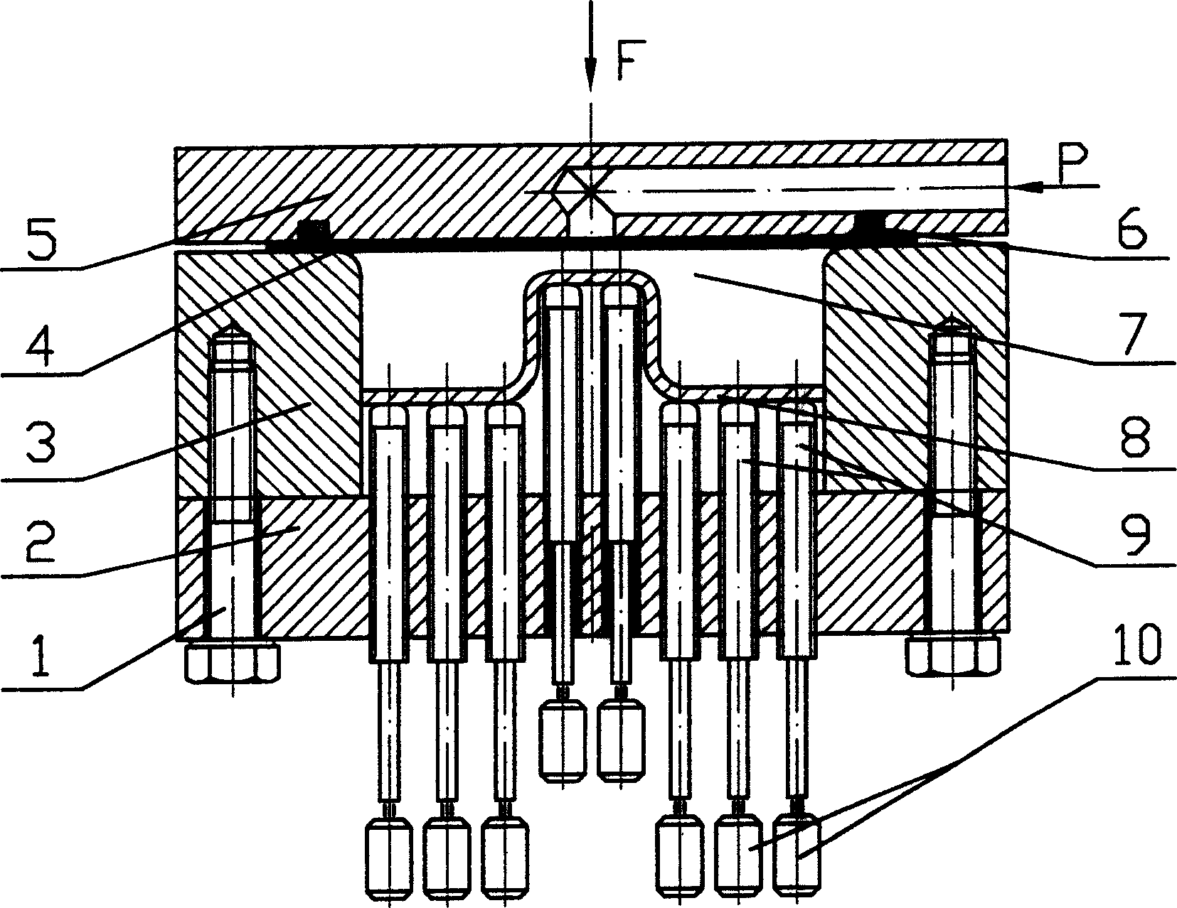
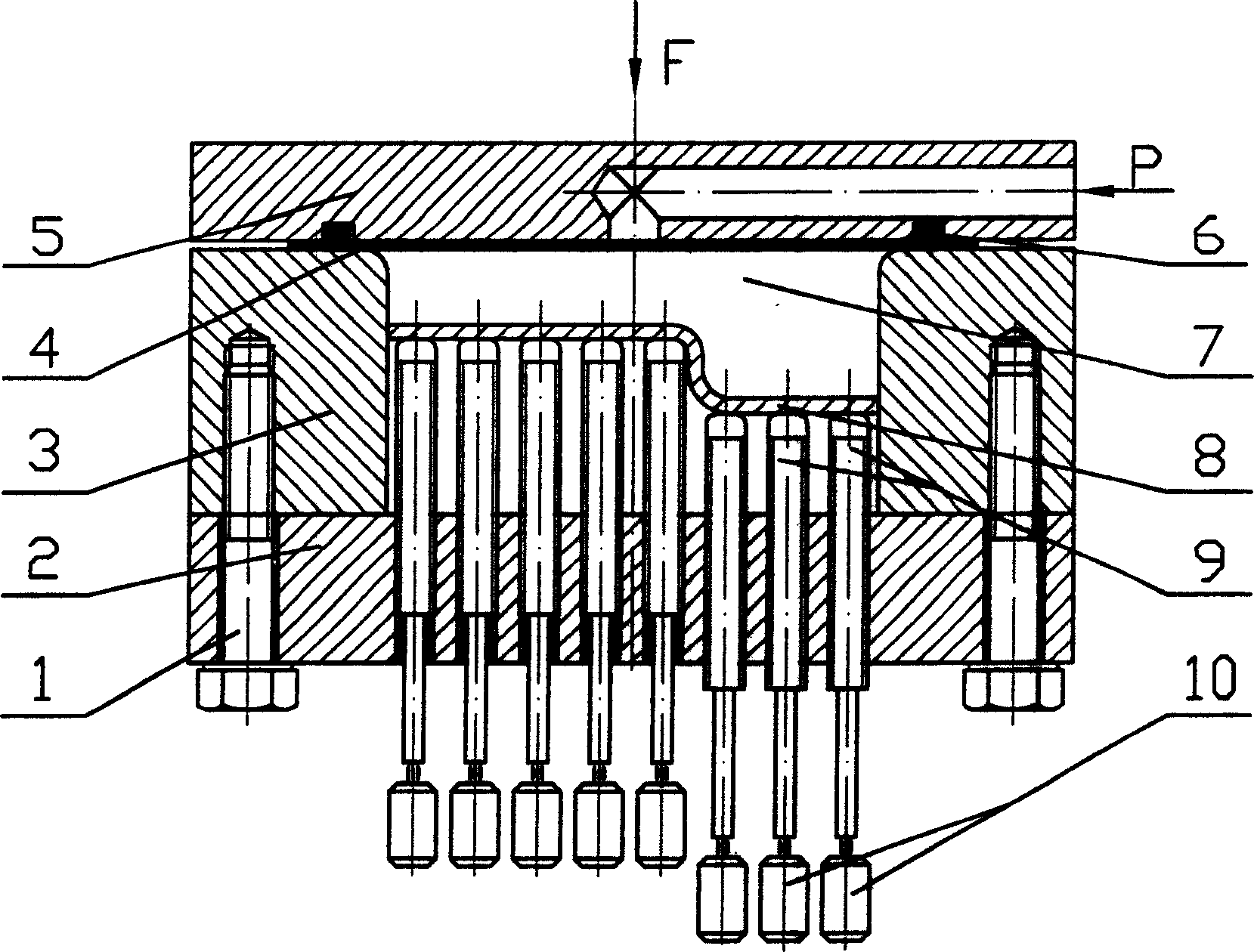
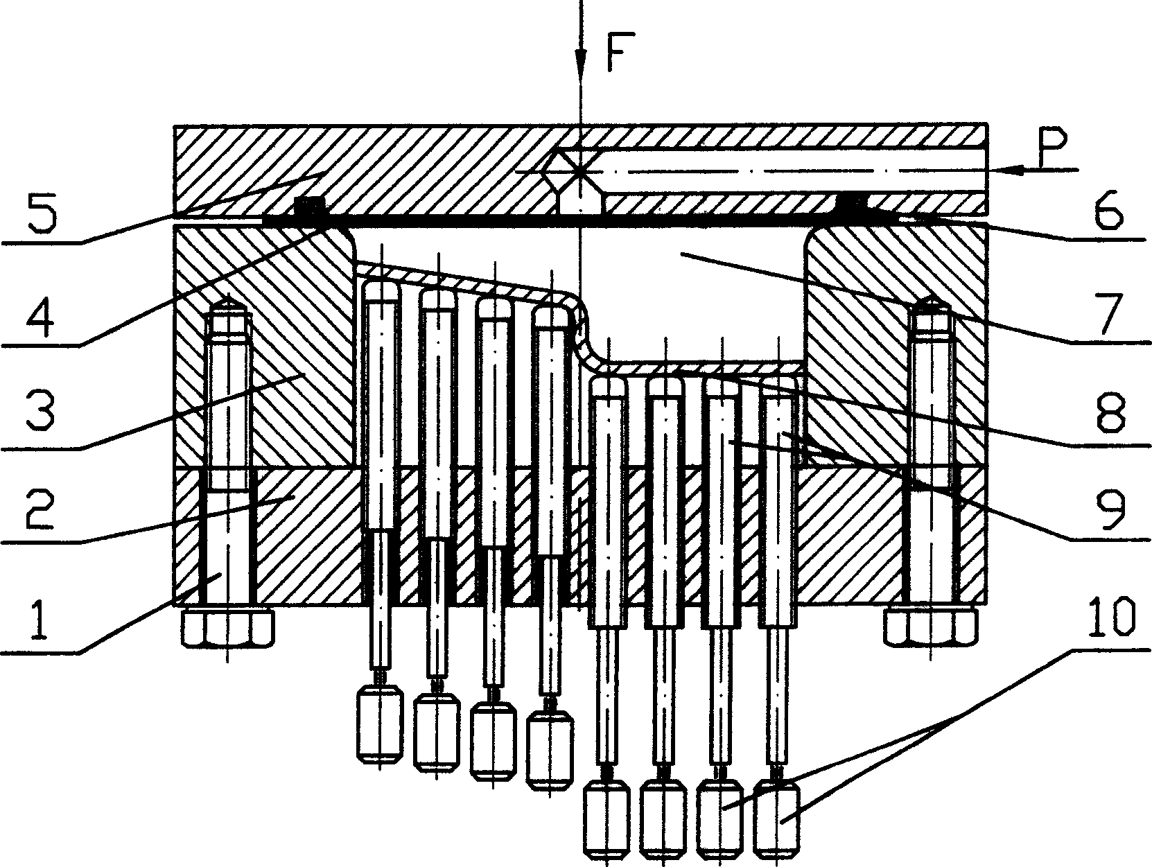
[0019] As shown in Fig. 1 (a), the hydraulic pressure or pneumatic forming device schematic diagram of forming a kind of double-box-shaped plate class part, hydraulic pressure or pneumatic forming device structure of the present invention comprises bolt 1, base 2, die seat 3, pressing plate 5, Sealing ring 6, die cavity 7, backing plate 8, movable unit group 9, motor 10. Die seat 3 central opening forms die cavity 7, and the cross section of die cavity is not only common circle, rectangle or square, also can be other shapes, there are several small punches (movable) in die cavity 7 unit) constitute the movable unit group 9 and the backing plate 8 corresponding to the size of the part to be formed, the punch is cylindrical, and the top of the punch contacting the backing plate can also be other cross-sectional shapes. Blank blanking, hydraulic or pneumatic loading and sealing, etc. are the same as conventional sheet metal hydraulic or pneumatic forming devices. The bolt 1 is u...


PUM


Abstract

The present invention relates to hydraulic or pneumatic plate forming process and apparatus. The forming process includes machining backing plate based on the bottom size of the part to be formed, regulating the movable units inside the mold cavity to form the contour of part bottom, setting the backing plate on the movable units, setting the blank on the mold cavity seat to constitute the mold cavity in the same cross section sizes as the part, pressing the edges of the blank with clamping plate, and introducing liquid pressure or air pressure inside the clamping plate to drive the blank to deform into required part. The forming apparatus has movable units distributed inside the mold cavity, motor for axial driving of the movable units and conventional sealing system. The present invention makes it possible to form different plate parts of different shapes in the same forming apparatus without machining corresponding molds.

Description

technical field [0001] The invention belongs to the field of mechanical engineering, specifically a hydraulic or pneumatic forming method and device for plates, mainly used for hydraulic or pneumatic forming of plates, and the materials can include magnesium alloys, aluminum alloys, titanium alloys and other non-ferrous metals and other ferrous metals . Background technique [0002] The hydraulic or pneumatic forming of plate parts is to use liquid or gas as the force transmission medium to act on the surface of the plate, so that it can be deformed and molded to form the desired shape. The characteristics of hydraulic or pneumatic forming are: (1) There is one less die or punch than the conventional sheet metal stamping forming device, thereby reducing the cost of the mold and the preparation time in the early stage; (2) The deformation of the sheet is more uniform under the drive of liquid or gas, Therefore, a greater amount of deformation can be obtained, the rigidity of...

Claims


Application Information

Patent Timeline
IPC IPC(8): B21D26/02B21D26/021B21D26/031
Inventor 郑文涛张士宏徐永超王中堂周丽新
Owner INST OF METAL RESEARCH - CHINESE ACAD OF SCI
Why Eureka
Try Eureka