
Speed regulating fan system with fault-tolerant capacity

A technology of fan system and fault tolerance, which is applied in the direction of control/regulation system, control system, and regulation of electrical variables, etc., which can solve the problems of supply risk, high price, excessive power consumption, etc., to reduce power consumption and noise, The speed is continuously adjustable to achieve the effect of fault tolerance

Active Publication Date: 2007-02-14
ZTE CORP
View PDF0 Cites 16 Cited by
  • Summary
  • Abstract
  • Description
  • Claims
  • Application Information

AI Technical Summary

Problems solved by technology

[0004] 1. The power supply voltage of the fan varies with the power supply voltage of the rack, which may cause poor heat dissipation when the power supply voltage is low, and excessive power consumption and extra noise when the voltage is high;
[0005] 2. The speed of the fan is not controlled, which may cause poor heat dissipation when the ambient temperature is high, and generate additional power consumption and noise when the ambient temperature is low;
The fan uses a special design (non-switching power supply mode) inside, the price is relatively expensive, and only a few suppliers produce it, so there is a supply risk;
[0010] 3. Use a separate switching power supply to generate a lower half-speed voltage, and the power supply of the fan can be switched between the input power supply voltage and the half-speed voltage, but such a control method cannot realize the continuous change of the fan speed and reduce the power The effects of loss and noise are limited;
Although it is more reliable to detect fan faults in this way, when the fan speed is required to be continuously adjustable, the fan current will change continuously, and a more accurate detection of the fan current is required to determine whether there is a fault, which increases the cost

Method used


Image

  • Speed regulating fan system with fault-tolerant capacity
  • Speed regulating fan system with fault-tolerant capacity
  • Speed regulating fan system with fault-tolerant capacity

Examples


Embodiment Construction

[0026] The implementation of the present invention will be further described in detail below in conjunction with the accompanying drawings.

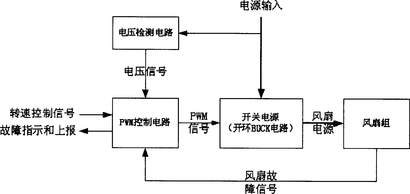
[0027] figure 1 is the overall block diagram of the system. The whole system is composed of input voltage detection circuit, PWM control circuit, switching power supply circuit and fan group. The PWM waveform output by the PWM control circuit is controlled by the speed control signal of the system and the detected voltage signal. This waveform controls the switching device of the switching power supply and outputs an appropriate voltage to supply power to the fan group. And when a fan failure is detected, certain adjustments can be made to the duty cycle of the PWM waveform.

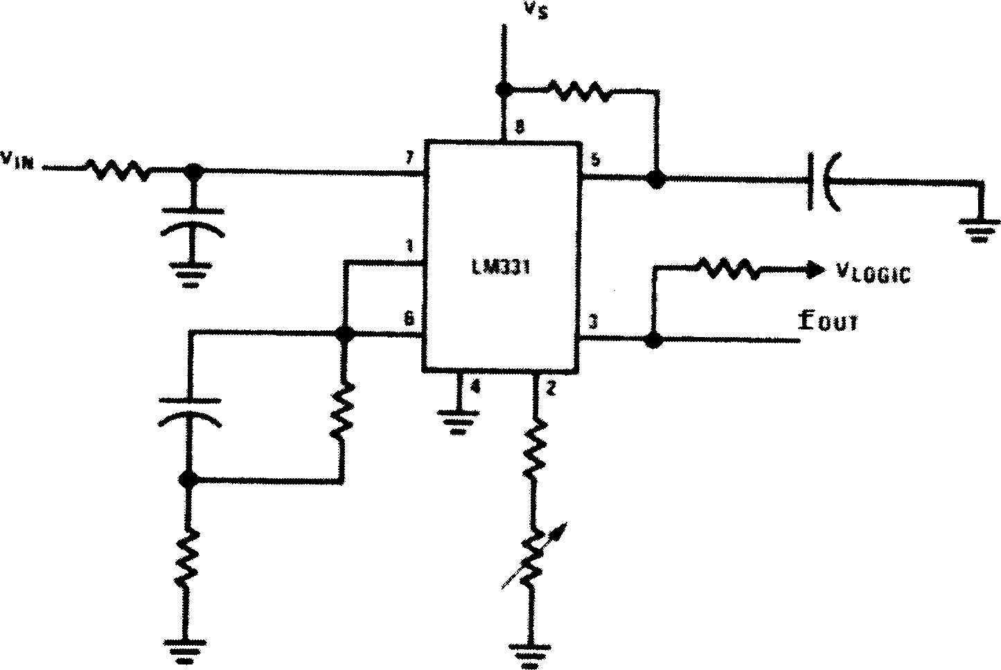
[0028] The input voltage detection circuit can be composed of one or more specialized voltage detection chips, such as ONSEMI's MC34161 voltage detection chip; it can also be composed of a general-purpose voltage comparator or operational amplifier, such as LM324...


PUM


Abstract

This invention relates to a fan regulation system with an error-tolerance ability including an input voltage testing circuit, a PWM circuit, a switch supply circuit and a fan set, in which, the control signal of rotation speed of the system and tested voltage signal control the output of the PWM waveforms, control the switch devices of a switch supply circuit and output a suitable voltage to the fan set, when the fan is tested to be faulty, the duty ratio of the PWm waveform can be adjusted.

Description

technical field [0001] The invention relates to a fan system for air cooling and heat dissipation of communication and large computers, in particular to a fan cooling device for communication equipment. Background technique [0002] In the fields of communications and large-scale computers, with the development of technology, the power consumption of equipment tends to increase gradually, which puts forward higher requirements for the heat dissipation performance and reliability of the heat dissipation system. At present, the main heat dissipation method in this field is to use cooling fans for active air cooling. In order to obtain better heat dissipation effects, the power of cooling fans also tends to increase, which leads to increased power consumption and noise of the fan system. [0003] In the traditional fan system, the fan is powered directly by the -48V power supply of the communication system. Under the current technical conditions, some problems are gradually ex...

Claims


Application Information

Patent Timeline
Patent Type & Authority Applications(China)
IPC IPC(8): H02P7/00H02P7/285G05F1/56G05F1/569H02P5/68H02P7/28H02P29/028
Inventor 韩正渭
Owner ZTE CORP
Learn More