
Planar display apparatus and installation device therefor

A flat-panel display and installation technology, which is applied in the direction of instruments, identification devices, TV system components, etc., can solve the problems that flat-panel display instruments are difficult to move, inconvenient to use, etc., to achieve increased strength, low noise, and improved degrees of freedom Effect

Inactive Publication Date: 2007-02-14
NANJING LG TONGCHUANG COLOR DISPLAYS SYST CO LTD
View PDF0 Cites 0 Cited by
  • Summary
  • Abstract
  • Description
  • Claims
  • Application Information

AI Technical Summary

Problems solved by technology

[0007] However, this method needs to increase the process of opening holes on walls with strong strength such as cement walls, and will leave permanent holes on the walls
And special tools for opening holes are required, so it is necessary to install flat-panel display instruments door-to-door by professionals
In addition, it is difficult to move the installed flat display instrument, which causes a lot of inconvenience in use

Method used


Image

  • Planar display apparatus and installation device therefor
  • Planar display apparatus and installation device therefor
  • Planar display apparatus and installation device therefor

Examples


Embodiment 1

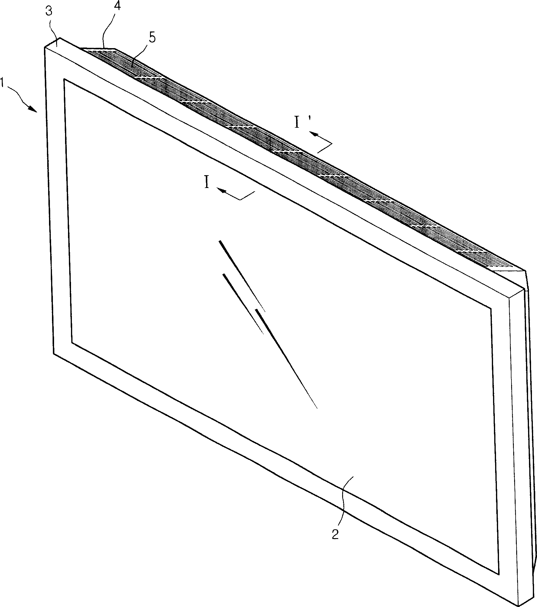
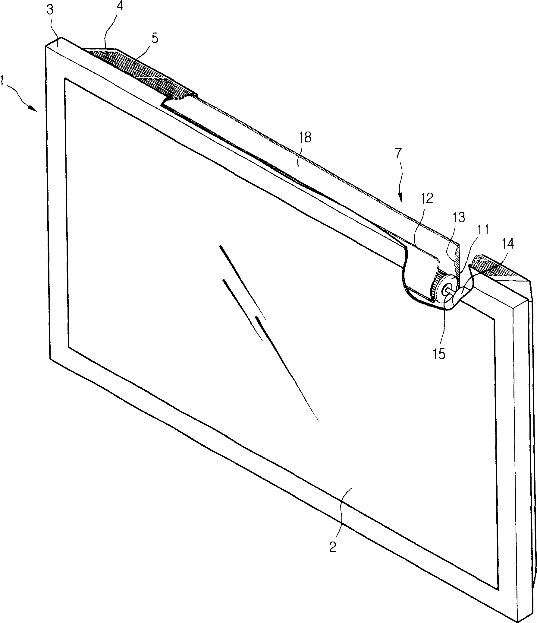
[0040] figure 1 is a schematic diagram of the plane display device in the first embodiment of the present invention.

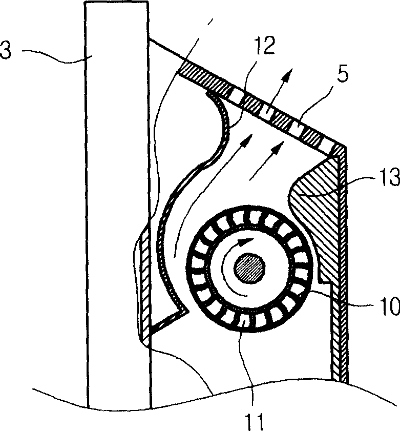
[0041] refer to figure 1 In the present invention, the plane display device 1 includes: a plane display module 2, supporting and protecting the front frame 3 in front of the plane display module 2, and supporting and protecting the rear cover 4 on the back of the plane display module 2. In addition, the upper edge of the rear cover 4 forms a rear cover opening 5 for discharging the high-temperature air inside the flat panel display device 1 to the outside. The above-mentioned rear cover opening 5 is a structure composed of a plurality of square holes, so it should be ensured that the strength of the rear cover 4 is not reduced. That is, the above-mentioned back cover opening 5 is a general term for the part where the high-temperature air inside the flat panel display 1 is discharged to the outside, and the inside thereof is formed in a shape in which a plura...

Embodiment 2

[0066] Figure 5 It is a side view of the installation device of the plane display instrument in the second embodiment of the present invention, refer to Figure 5 The structure of the installation device is described in detail as follows:

[0067] First, the side wall 50 can be installed in close contact with the back of the flat display device 1 in a state where the weight of the flat display device mounting device is supported by the ground 51 . This is because the back of the above-mentioned flat display device 1 has no openings for sucking or discharging air, so there is no need for any distance between the back of the flat display device 1 and the side walls 50 . When the flat display device 1 is installed as above, it can be positioned at a higher position on the side wall 50 when the flat display device 1 is supported by the ground.

[0068] A general flat-panel display may be tilted forward and backward. Therefore, in order to place the flat-panel display at a highe...


PUM


Abstract

Disclosed is a planar display apparatus comprising; a planar display module; a rear cover protecting the rear part of the planar display module; an opening part disposed on the edge of the rear cover passing through the same to tightly connect the rear of the cover to the wall. The planar display apparatus achieves a thinner, simple and abundant radiating effect, minimizes the moving noise, improves the installation freedom and strengths of the rear cover. At the same time, the main body of the planar display apparatus is tightly attached to the wall according to the structural variation, therefore, a user can install the planar display on the wall conveniently to increase the interior utilization ratio. Also, the planar display is not only designed to tightly attaching to the wall, but also designed to be installed randomly according to the user's plan, therefore to improve the convenience.

Description

technical field [0001] The present invention relates to a flat display device, more specifically, it relates to an installation device for making the internal heat of the flat display device diffuse rapidly to the outside, thereby improving the working reliability of the flat display device and facilitating the installation of the flat display device. technical background [0002] Different from general cathode ray tubes, flat panel display devices consist of driving circuits arranged in a matrix, and each pixel has a different light emitting state, thus forming the entire screen. Unlike the above-mentioned cathode ray tubes, this type of flat panel display device is highly popular among users because of its small size and takes up little space in a narrow indoor space, and its utilization rate has increased significantly in recent years. The flat display module of the above flat display device is divided into liquid crystal display (Liquid Crystal Display: LCD), field emiss...

Claims


Application Information

Patent Timeline
IPC IPC(8): H05K7/20H05K5/03G09F9/00
CPCH04N5/65H05K7/20954
Inventor 朴相暾
Owner NANJING LG TONGCHUANG COLOR DISPLAYS SYST CO LTD
Learn More