Color filter and manufacturing method

A color filter and color filter layer technology, which is applied in the field of color filters, can solve problems such as insufficient color saturation, and achieve the effects of improving color saturation, increasing contrast, and simplifying complexity

Active Publication Date: 2007-02-21
AU OPTRONICS CORP
View PDF1 Cites 16 Cited by
  • Summary
  • Abstract
  • Description
  • Claims
  • Application Information

AI Technical Summary

Problems solved by technology

[0007] In view of this, one of the objects of the present invention is to provide a color filter that can solve

Method used


Image

  • Color filter and manufacturing method
  • Color filter and manufacturing method
  • Color filter and manufacturing method

Examples


Embodiment Construction

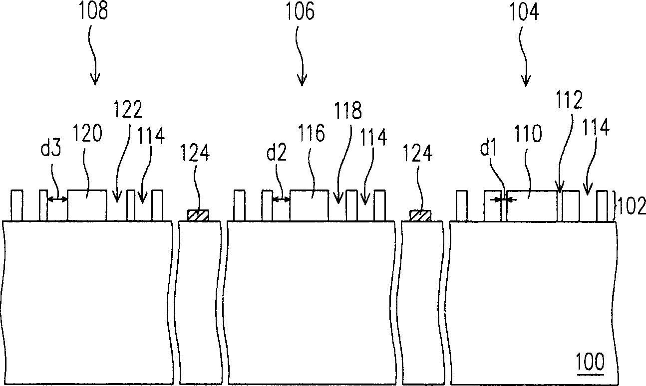
[0069] figure 1 What is shown is the top view of the color filter according to the first embodiment of the present invention. figure 2 shown along the figure 1 Sectional view of the A-A' section line in the middle.

[0070] First, please also refer to figure 1 and figure 2 , the color filter includes a substrate 100 and a color filter layer 102 . The substrate 100 is, for example, a transparent substrate such as a glass substrate.

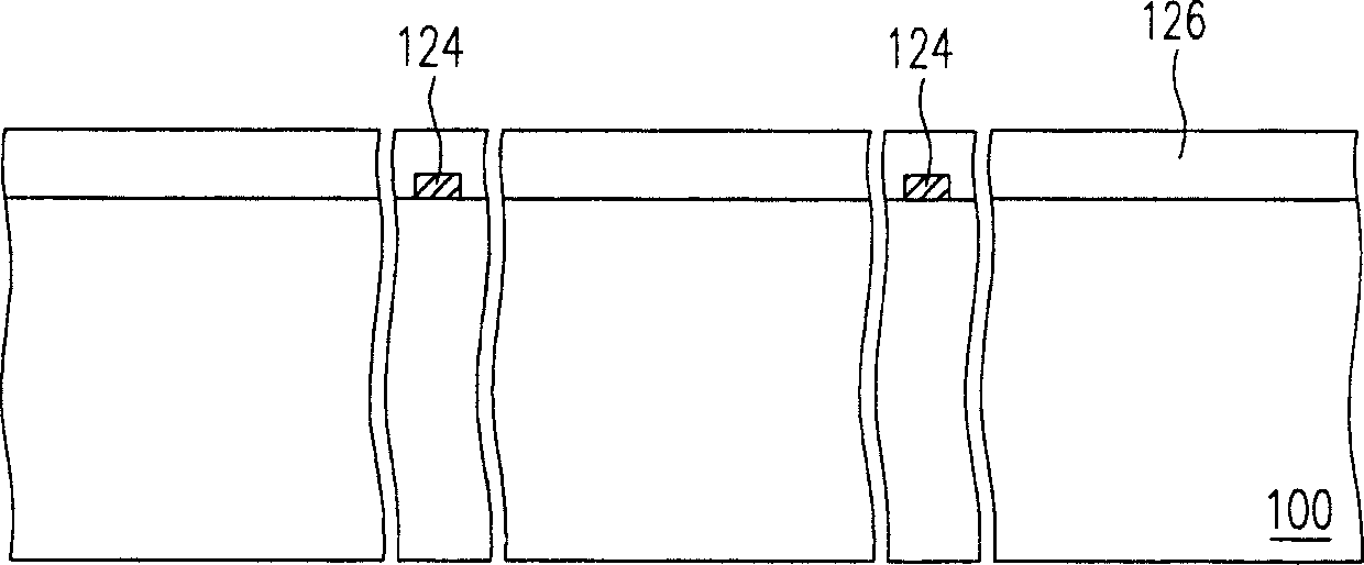
[0071] The color filter layer 102 is disposed on the substrate 100 and includes a red photonic crystal structure 104 , a green photonic crystal structure 106 and a blue photonic crystal structure 108 . The material of the color filter layer 102 is, for example, a dielectric material such as silicon nitride.

[0072] The red photonic crystal structure 104 includes a first defective resonant cavity 110 , and has a plurality of first holes 112 around the first defect resonant cavity 110 and a plurality of fourth holes 114 arranged periodically...


PUM


Abstract

A color filter consists of base and color filtering layer being set on base plate and being formed by red photon crystal structure with multiple the first holes, green photon crystal structure with multiple the second holes and blue photo crystal structure with multiple the third holes. It is featured as setting holes diameter of the first holes to be less then that of the second ones and hole diameter of the second holes to be less than that of the third ones.

Description

technical field [0001] The present invention relates to a color filter, and in particular to a color filter using a photonic crystal structure as a color filter layer. Background technique [0002] The cathode ray tube (Cathode Ray Tube, CRT) has been monopolizing the display market in recent years due to its excellent display quality and economy. However, for the environment where individuals operate most terminals / display devices on the table, or from the perspective of environmental protection, if the trend of energy saving is predicted, cathode ray tubes still have many problems in terms of space utilization and energy consumption, and There is no effective solution to the demands of lightness, thinness, shortness, smallness and low power consumption. Therefore, thin film transistor liquid crystal displays (Thin Film Transistor Liquid Crystal Display, TFT LCD) with superior characteristics such as high image quality, increased space utilization efficiency, low power con...

Claims


Application Information

Patent Timeline
IPC IPC(8): G02B5/23G02F1/1335
Inventor 吴佩勋蓝英哲王自豪许家旸
Owner AU OPTRONICS CORP
Why Eureka
Try Eureka