
Applying device

A technology of coating device and coating liquid, which is applied in the direction of spraying device, device for coating liquid on the surface, coating, etc., can solve the problems of increasing work load, difficulty in ensuring the quantification of coating amount, etc., and achieves reduction of vibration and Undulating, easily adjustable effect

Inactive Publication Date: 2007-02-28
TOKYO OHKA KOGYO CO LTD
View PDF7 Cites 5 Cited by
  • Summary
  • Abstract
  • Description
  • Claims
  • Application Information

AI Technical Summary

Problems solved by technology

However, since the pipe (pipe) from the liquid delivery pump to the slit nozzle is long, it is difficult to ensure the quantitativeness of the coating amount due to the expansion and contraction of the pipe, etc.
[0023] In addition, although Patent Document 7 describes the invention of providing a liquid delivery pump integrally with the slit nozzle, in this case, the liquid delivery pump must also be taken out when replacing the slit nozzle.
Therefore, it is necessary to improve the work accuracy, which increases the work load and requires a long wait until re-coating

Method used


Image

  • Applying device
  • Applying device
  • Applying device

Examples


Embodiment Construction

[0044] Embodiments of the present invention will be described below based on the drawings.

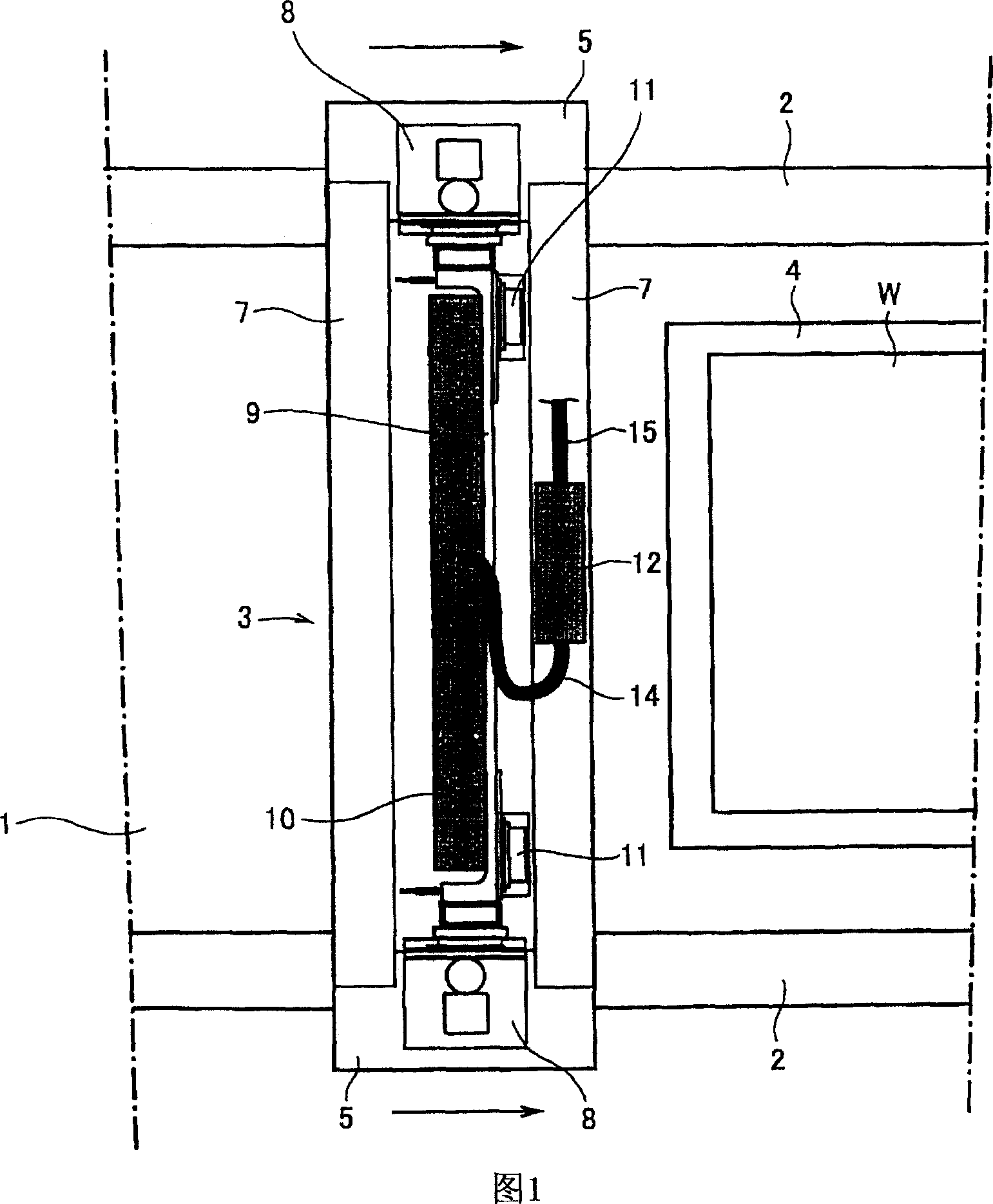
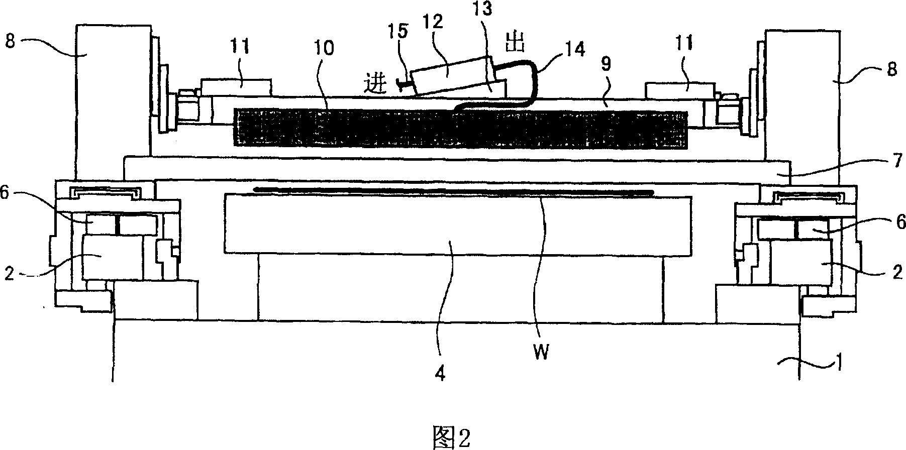
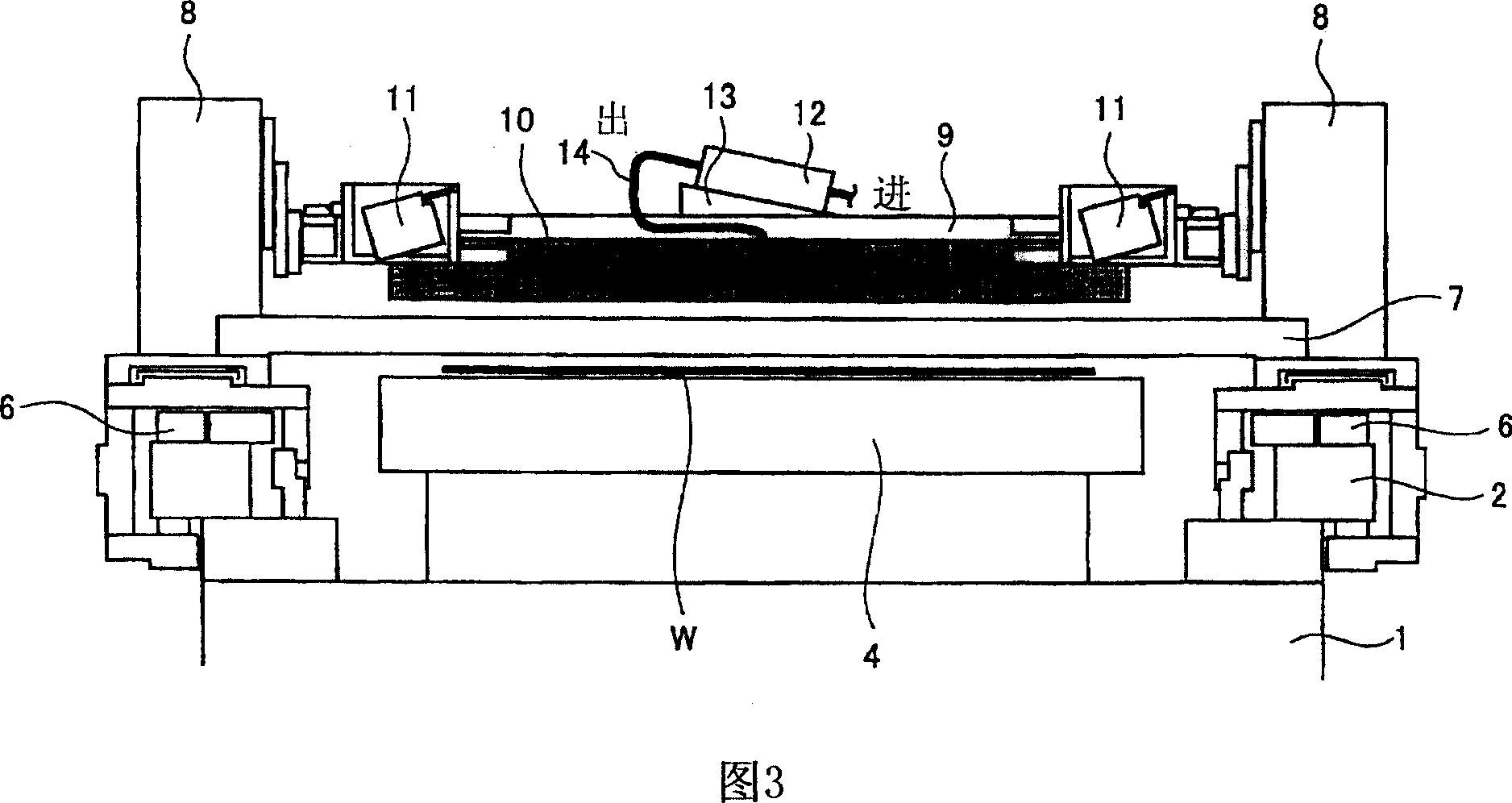
[0045] FIG. 1 is an enlarged plan view showing part of a coating device according to an embodiment of the present invention. In addition, FIG. 2 is a view in the direction of A in FIG. 1 , FIG. 3 is a view in the direction of B in FIG. 1 , and FIG. 4 is an enlarged side view for explaining the mounting state of the slit nozzle.

[0046] As shown in FIGS. 1 to 3 , the coating device according to this embodiment is supported by a base 1 .

[0047] On the base 1, a pair of rails 2, 2 are provided in parallel in the horizontal direction, and a door-shaped moving mechanism 3 is engaged with the pair of rails 2, and on the base 1, a platform for placing a glass substrate W and the like is provided. The substrate mounting platform 4 .

[0048] The gate-shaped moving mechanism 3 has a gantry frame 5 as a moving body in a shape surrounding the rail 2 , and an air cushion 6 forming a gap with ...


PUM


Abstract

The invention provides a coater ensuring constant feeding of a coating solution and reducing vibration generated during movement of the slit nozzle. A tube-separating pump (12) is arranged as a coating solution supplying pump at the central part of the width direction of an anterior connecting girder (7) based on a coating direction as a reference. The tube-separating pump (12) is operated by applying a symmetrical pressure on a circumferential part of the tube by a non-compressed fluid. The tube-separating pump (12) is slantwise fixed to a wedge member (13) on the connecting girder (7) in such a manner that outlet thereof is arranged upwards and inlet thereof is arranged downwards. Gas is prevented from entering by this slantwise configuration. And the configuration by which liquid retention is prevented at the outlet and the inlet is provided which is advantageous for preventing dropping, and the like.

Description

technical field [0001] The present invention relates to a coating device for coating a developing solution, a cleaning agent, an SOG solution, a resist, and the like on substrates such as glass substrates and semiconductor wafers. Background technique [0002] In the manufacturing process of liquid crystal (LCD), PDP (plasma display), semiconductor elements, etc., coating equipment is used to form various protective films on substrates, or to apply cleaning agents or developing solutions. [0003] As a conventional coating device, for example, as shown in Patent Document 1, there is known a coating device that drips a coating liquid from a nozzle to the center of a substrate, and then uniformly coats the coating liquid on the substrate by centrifugal force generated by rotating the substrate. A spin-coating type of coating liquid, or a type that uniformly coats a substrate by spraying. [0004] In such a spin coating type and a spray type, the effective amount of coating li...

Claims


Application Information

Patent Timeline
Patent Type & Authority Applications(China)
IPC IPC(8): B05C5/02B05C11/10B05B13/04
CPCB05C5/0225B05C11/1002G03F7/16H01L21/027
Inventor 升芳明熊泽博嗣山口和伸
Owner TOKYO OHKA KOGYO CO LTD
Learn More