Supercharge Your Innovation With Domain-Expert AI Agents!

Synchronizing signal detecting device

A technology of synchronization signal and detection device, which is applied in multiple input and output pulse circuits and other directions, can solve the problems of limiting the frequency range of the synchronization signal to be detected, lack of flexibility and expandability of the circuit, and achieves low and flexible internal clock signal requirements. Strong and expandable effect

Active Publication Date: 2007-02-28
HUAWEI TECH CO LTD
View PDF0 Cites 15 Cited by
  • Summary
  • Abstract
  • Description
  • Claims
  • Application Information

AI Technical Summary

Problems solved by technology

[0008] First, the connection relationship between the clock generator, the counter and the XOR gate causes the frequency of the internal clock signal generated by the clock generator to be at least twice the frequency of the externally input synchronous signal, which limits the frequency range of the input synchronous signal to be detected;
[0009] Secondly, the synchronous signal detection device limits the input terminal D of flip-flop 1 to a high level, which makes the circuit lack of flexibility and expandability

Method used


Image

  • Synchronizing signal detecting device
  • Synchronizing signal detecting device
  • Synchronizing signal detecting device

Examples


Embodiment Construction

[0040] In order to express the object, technical solution and effect of the present invention more clearly and completely, the present invention will be further described in detail below in conjunction with the accompanying drawings and embodiments.

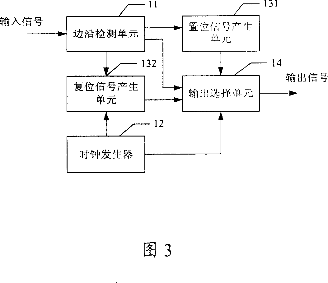
[0041] 3 is a schematic diagram of the composition of the synchronization signal detection device of the present invention, which mainly includes an edge detection unit 11 , a clock generator 12 , a set signal generation unit 131 , a reset signal generation unit 132 and an output selection unit 14 . specifically:

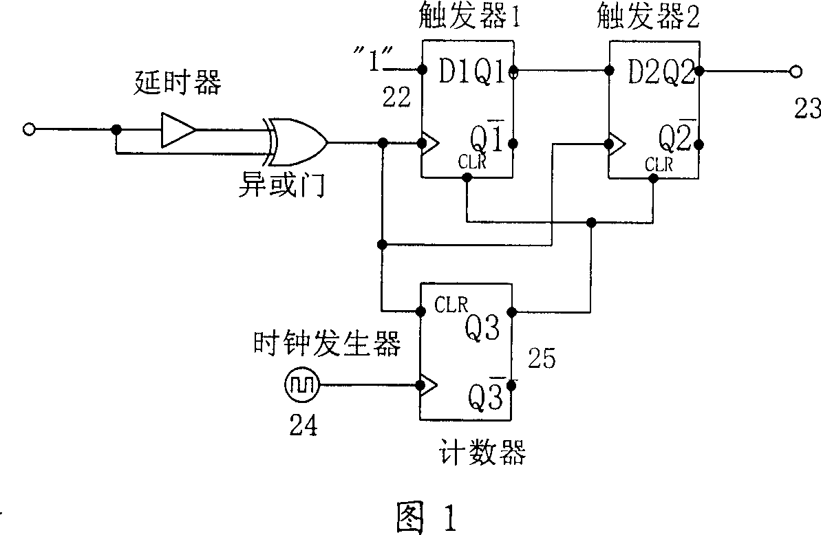
[0042]Edge detection unit 11 is used to detect the edge of the input synchronous signal, and when the synchronous signal edge is detected, a pulse signal is generated, otherwise, a level signal is generated; the edge detection unit can be an upper edge detection circuit, a lower edge detection circuit and a dual Either of the edge detection circuits. The pulse signal it generates can be a high-level pulse signal or a ...


PUM


Abstract

The invention relates to a synchronous signal detector, which comprises: edge detector for detecting the edge of input synchronous signal; clock generator for generating internal clock signal; impulse signal detector for generating set signal when receiving the impulse signal output by the edge detector and generating reset signal when receiving the voltage signal output by the edge detector; an output selector for selectively output the impulse signal or the internal clock signal based on the output signal of impulse signal detector. The invention has wide frequency width of detectable external synchronous signal and low demand on the internal clock signal.

Description

technical field [0001] The invention relates to a synchronous signal detection technology, in particular to a synchronous signal detection device. Background technique [0002] The synchronous signal detecting device can take the synchronous signal as the output when the synchronous signal is input; and can take the clock signal generated by the internal clock generator as the output when the fixed level signal (fixed high level or low level signal) is input. [0003] An existing synchronization signal detection device is shown in Figure 1 and Figure 2, Figure 1 is a synchronization signal detection module of the prior art synchronization signal detection device, Figure 2 is a gating module of the prior art synchronization signal detection device. The whole device includes a signal input terminal 21, a signal output terminal 26, a delayer and an XOR gate, a flip-flop 1, a flip-flop 2, a clock generator 24, a counter 25, an inverter, a NAND gate 1, and a NAND gate 2 NAND gat...

Claims


Application Information

Patent Timeline
Patent Type & Authority Applications(China)
IPC IPC(8): H03K5/22
Inventor 李定
Owner HUAWEI TECH CO LTD
Features
  • R&D
  • Intellectual Property
  • Life Sciences
  • Materials
  • Tech Scout
  • Unparalleled Data Quality
  • Higher Quality Content
  • 60% Fewer Hallucinations
Learn More