Engine crankshaft balance shaft mechanism

A balance shaft and engine technology, applied in the direction of inertial force compensation, etc., can solve the problems of insufficient compact structure, large amplitude of the balance shaft system, etc., and achieve the effects of compact structure, reduced noise, and simplified tensioning mechanism

Inactive Publication Date: 2007-03-07
CHERY AUTOMOBILE CO LTD
View PDF0 Cites 16 Cited by
  • Summary
  • Abstract
  • Description
  • Claims
  • Application Information

AI Technical Summary

Problems solved by technology

[0005] In order to solve the technical problems of large vibration amplitude and insufficient compact structure of the balance shaft system and the deficiencies of the prior art, the pres...

Method used


Image

  • Engine crankshaft balance shaft mechanism

Examples


Embodiment Construction

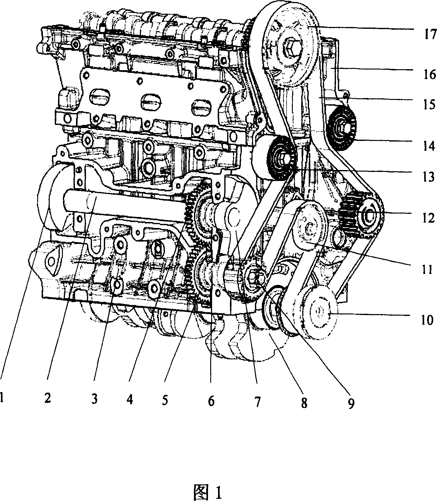
[0016] In the embodiment shown in Fig. 1, a kind of engine crankshaft balance shaft mechanism comprises the balance shaft 2, drive shaft 6, drive shaft 6, Gears 4, 5, balance shaft cover; balance shaft gear 4 is installed on the front end of balance shaft 2, and balance shaft gear 4 meshes with balance shaft gear 5 on drive shaft 6; balance shaft 2 is installed on the side of cylinder body 3; driven by timing belt 15 shaft 6, and drives the balance shaft 2 through the meshing balance shaft gears 4,5.

[0017] As shown in Figure 1, inside the cylinder head 16, the timing belt 15 installed on the crankshaft timing gear 10 on the crankshaft 8 passes through the belt tensioner 11, the belt gear 9, the idler 13, and the camshaft timing gear 17 in sequence. , idler wheel 14, water pump gear 12 form belt transmission chain.

[0018] An oil hole can also be drilled in the middle of the balance shaft, and then one end is blocked, and a corresponding lubricating oil groove is added to ...


PUM


Abstract

This invention discloses one motor curve axis balance structure, which comprises the following parts: balance axis matched weight distributed along 180 degree direction, drive axis, one pair of meshed balance gear, and balance axis cover with front end fixed with one balance axis gear and other end with one balance gear. The invention is characterized by fixing balance axis by side of cylinder and positive band drive axis to drive balance axis through balance axis gear.

Description

technical field [0001] The invention relates to an engine crankshaft balance shaft mechanism, in particular to an engine crankshaft balance shaft mechanism placed sideways on a cylinder block. Background technique [0002] Engine vibration and noise directly affect the comfort of the vehicle and the structural strength of the engine itself. Excessive vibration will lead to the service life and performance of related parts. Generally speaking, it is difficult to balance the reciprocating inertial force of the engine crank-link mechanism with an odd number of cylinders, and it is usually necessary to add a balance shaft to balance, such as 3-cylinder and 5-cylinder engines; in order to work more smoothly and ensure the comfort of the passengers, Sometimes engines with even cylinders also have a balance shaft added. [0003] Generally, the engine crankshaft balance shaft mechanism is arranged at the lower part of the engine, in the oil pan, including the balance shaft housing,...

Claims


Application Information

Patent Timeline
IPC IPC(8): F16F15/26
Inventor 朱小平
Owner CHERY AUTOMOBILE CO LTD
Why Eureka
Try Eureka